S&s Ignition Wiring Diagram – We’ll begin by looking at the various types of terminals on the ignition switch. These include the terminals that are for the Ignition switch, Coil, and Accessory. Once we’ve determined the function of the terminals we can recognize the various parts of the ignition wiring. We’ll also discuss the functions and the Coil. Then, we will turn our attention towards the accessory terminals.
Terminals for ignition switches
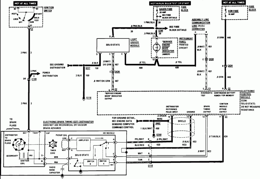
An ignition switch has three switches. They supply the voltage of the battery to many different locations. The first switch is used to drive the choke by pushing it. Then, the third switch is used to control the ON/OFF setting. Different manufacturers use different color-coding methods to identify different conductors. We’ll discuss this in a different article. OMC follows this system. The ignition switch also includes an option to connect a tachometer.
Although the majority of ignition switch terminals don’t have an original number, they may have a different one. Check the electrical continuity to determine if they’re connected to the ignition switch correctly. A multimeter is an excellent tool to check the continuity. After you’re happy with the continuity of your wires, you will be able to install the new connector. If you are using an ignition switch supplied by the manufacturer the wiring loom may be distinct from the one that is in your car.
First, understand the differences between the ACC and secondary outputs. The ACC and IGN terminals are the default connections on the ignition switch. the START and IGN terminals are the principal connections for stereo and radio. The ignition switch is accountable to turn the car’s engines on and off. The terminals for the ignition switch on older cars are identified with the initials “ACC” as well as “ST” (for individual magneto wires).
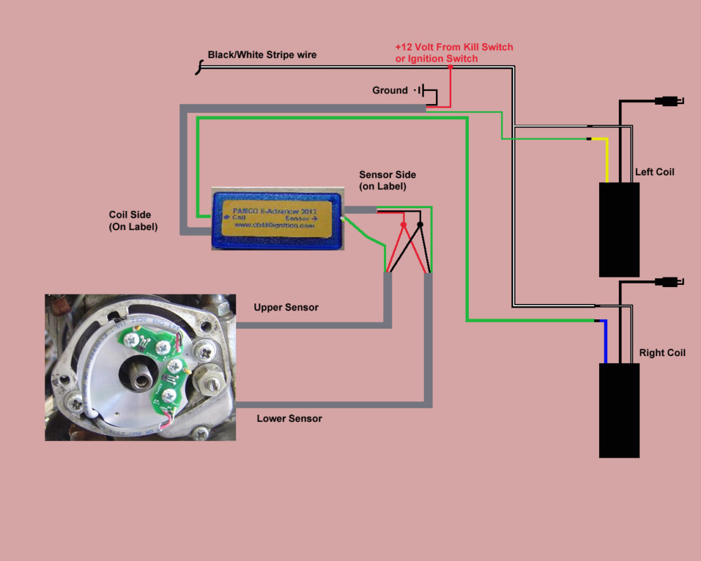
Terminals for coil
Understanding the terminology is the first step in determining which type of ignition coil you’ve got. The diagram of the basic ignition wiring illustrates a variety of connections and terminals. There are two primary and one secondary. Each coil is operating at a certain voltage. The first step to determine the type you’re using is to examine the voltage at S1 or the primary terminal. To determine if it is an A, C, or B coil, you should also check the resistance of S1.
The chassis’ negative needs to be connected to the side of low-tension. This is the base of the wiring for ignition. The high-tension component supplies the spark plugs with positive. It is necessary to suppress the body of the coil’s metal be connected to the chassis, however it isn’t essential. A wiring diagram can also show the connection between the positive and negative coil terminals. In some instances you’ll discover that an ignition coil that is malfunctioning can be diagnosed with scans at an auto parts store.
The black-and-white-striped wire from the harness goes to the negative terminal. Positive terminal receives a second white wire, which includes a black trace. The contact breaker is attached to the black wire. You can remove the black wire from the plug housing using a paper clip in case you are uncertain about the connections. It’s also essential to make sure that the terminals don’t bend.
Accessory terminals
The wiring diagrams for the ignition show the different wires used to provide power to the various parts of the car. There are usually four different colors of terminals connected to each part. The red color is for accessories, yellow is the battery and green is the starter solenoid. The “IGN terminal is used to start the car, controlling the wipers and various other functions. The diagram shows how to connect the ACC and ST terminals to the rest of the components.
The terminal BAT connects the battery to the charger. Without the battery the electrical system will not get started. Furthermore, the switch won’t begin to turn on. The wiring diagram will tell you where to find your car’s battery. The ignition switch is connected to the battery of your car. The BAT Terminal is connected to the battery.
Certain ignition switches have an additional position in which users can modify their outputs and manage them without having to turn on the ignition. Sometimes, a customer wants to use the auxiliary output separate from the ignition. In order for the auxiliary output be used, connect the connector to the same shade as the ignition. Then , connect it to the ACC end of the switch. This feature of convenience is fantastic, but there is one difference. The majority of ignition switches are set to have an ACC position when the vehicle is in the ACC position, but they’re set to the START position when the vehicle is in the IGN position.
Gallery of S&s Ignition Wiring Diagram
Gallery of S&s Ignition Wiring Diagram


