Bosch Ignition Switch Wiring Diagrams – Let’s start by looking at the different types terminals found on the ignition switch. They include terminals for Coil, Ignition Switch, and Accessory. Once we know the terminals used, we can begin to recognize the various parts of the Bosch Ignition Switch Wiring Diagrams. We will also discuss the function of the Ignition switch and Coil. We will then focus on the accessories terminals.
Terminals for ignition switches
An ignition switch is comprised of three switches. They transmit the voltage of the battery to different places. The choke is powered by the first switch. The second switch is responsible for the ON/OFF of the ignition switch. Every manufacturer has its own color-coding system, which we’ll go over in a separate article. OMC uses the same method. An adapter is included on the ignition switch, allowing the installation of a Tachometer.
Although most ignition switch terminals can be duplicated, the numbers may not be in line with the diagram. To ensure that your wires are plugged in to the switch you must verify their continuity. This can be done using a cheap multimeter. After you’re happy with the continuity of the wires, then you’ll be able to install the new connector. If your car has an ignition switch that is installed the wiring diagram may differ.
It is important to understand how the ACC outputs and auxiliary outputs function in order to connect them. The ACC and IGN terminals are the default connections on your ignition switch, and the START and IGN terminals are the principal connections for stereo and radio. The ignition switch is the one that turns the engine of your car on and off. In older vehicles, the ignition switch terminals are identified with the initials “ACC” and “ST” (for distinct magnetic wires).
Terminals for coil
To determine the type of ignition coil, the first step is to know the definition of. The diagram of the basic ignition wiring illustrates a variety of connections and terminals. There are two primary and one secondary. Each coil is operating at a certain voltage. The first step to determine which kind you’re using is to examine the voltage of S1 or the primary terminal. S1 should also be checked for resistance to determine if it’s an A, Type B, or A coil.
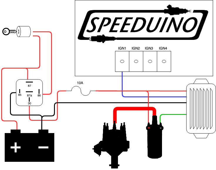
The chassis’ negative must be connected to connect the coil’s low-tension end. This is what’s called the ground in the diagram of the ignition wiring. The high-tension side delivers the positive power direct to the spark plugs. The aluminum body of the coil has to be connected to the chassis for suppression however it’s not electrically required. A wiring diagram can show the connection between the positive and negative coils. Sometimes, a damaged ignition coil can be detected by a scan done at an auto repair shop.
The black-and-white-striped wire from the harness goes to the negative terminal. The other white wire is black with a trace on it, and it goes to the positive terminal. The black wire connects to the contact breaker. To check the connections between the two wires use a paperclip to lift them out of the housing. Be sure to check that the terminals aren’t bent.
Accessory terminals
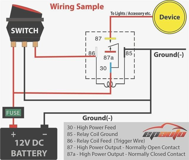
Diagrams of ignition wiring depict the wires that supply power to different parts of the car. Typically, there are four different color-coded terminals for each component. The accessories are red while the battery is yellow, the starter solenoid is green. The “IGN” terminal allows you to start your car, operate the wipers, and any other functions. This diagram shows how to connect ACC and ST terminals to the other components.
The terminal BAT holds the battery. Without the battery, the electrical system does not get started. In addition the switch isn’t turned on. You can view the wiring diagram of your car to see where the batteries of your car are situated. The ignition switch as well as the battery are connected via accessory terminals. The BAT connector is connected to your battery.
Some ignition switches come with a separate “accessory” location, which allows users can manage their outputs without the ignition. Sometimes, customers may wish to use the auxiliary input independently of the ignition. For the auxiliary output to be used, connect the connector to the same shade as that of the ignition. Then , connect it to the ACC end of the switch. This feature is convenient, but it has one significant difference. A lot of ignition switches can be programmed to have an ACC position when the vehicle has been moved into the ACC position. They’ll also be in START mode when the vehicle has entered the IGN position.
Gallery of Bosch Ignition Switch Wiring Diagrams
Gallery of Bosch Ignition Switch Wiring Diagrams


