Car Ignition Coil Wiring Diagram – We’ll begin by looking at different types terminals found in an ignition switch. They are terminals for Coil, Ignition Switch, and Accessory. Once we have established the purpose of these terminals are for We will then determine the various parts of the Car Ignition Coil Wiring Diagram. We’ll also discuss the functions of the Ignition switch and Coil. Following that, we’ll shift our attention to Accessory terminals.
The terminals are for ignition switches.
Three switches are located on the ignition switch. Each of these three switches is able to feed the battery’s voltage to various locations. The choke is powered by the first switch. The second switch controls the ON/OFF of the ignition switch. Different manufacturers employ various color codes for the various conductors. This is explained in another article. OMC utilizes the same system. The ignition switch is also equipped with a connector for adding a tachometer.
While many ignition switch terminals may not be original, the numbers of each one might not match the diagram. Before plugging into the ignition switch, make sure to check the continuity. This can be done using a simple multimeter. After you’re sure that the wires are in good continuity then you can connect the new connector. The wiring loom of an ignition switch that’s supplied by the manufacturer will differ from the one you have in your car.
To connect the ACC outputs to the auxiliary outputs on your car, you need to first understand the way these two connections function. The ACC and IGN terminals are the default connection on your ignition switch. the START and IGN terminals are the principal connections for the radio and stereo. The ignition switch is the one that controls the engine of your car. Older cars are identified with the alphabets “ACC”, “ST”, (for individual magneto cables) at their ignition switch terminals.
Terminals for coil
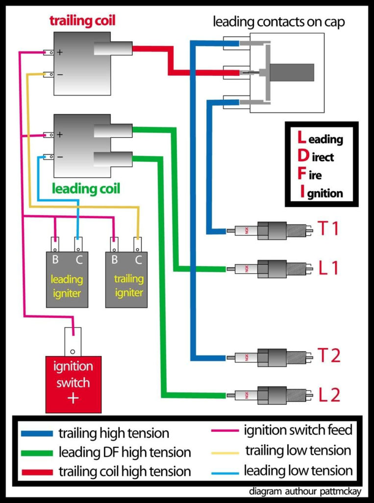
To determine the type of ignition coil, the first step is to know the terms. In a typical ignition wiring diagram you’ll see various terminals and connections, including two primary and two secondary. Each coil comes with its own operating voltage. To determine what kind of coil you own, the first step is to test the voltage at the S1 primary terminal. S1 should also be checked for resistance in order to identify if it’s an A, Type B, or A coil.
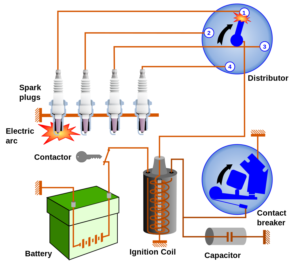
The coil’s low-tension side should be connected to the chassis’ less. This is what is known as the ground for the wiring for ignition. The high-tension end is a positive connection to the sparkplugs. To prevent noise, the coil’s body metal must be connected to the chassis. This is not necessary to use electricity. The wiring diagram will show the connection between the positive and negative coil terminals. Sometimes, a visit to an auto parts store could identify a problem with the ignition wire.
The black-and-white-striped wire from the harness goes to the negative terminal. The negative terminal is served by the black trace that’s connected to the white wire. The contact breaker is linked to the black wire. You can remove the black wire from the housing of the plug using a paper clip in case you are uncertain about the connection. Make sure you check that the terminals have not been bent.
Accessory terminals
Diagrams of ignition wiring illustrate the wires that provide power to various components of the car. Each component has four distinct colored connections. To identify accessories, red stands the starter solenoid’s color, yellow is for battery, and blue is for accessories. The “IGN terminal lets you start the car, control the wipers, or any other features that operate. The below diagram shows how to connect the ACC terminal and ST terminals to the other components.
The terminal BAT holds the battery. Without the battery, the electrical system does not begin. A dead battery can make the switch stop turning on. If you don’t know the exact location where the battery in your car is situated, you can examine your wiring diagram to see where it is. Your car’s accessory terminals connect to the ignition switch as well as the battery. The BAT Terminal is connected to the Battery.
Some ignition switches offer an additional “accessory position” that allows users to adjust their outputs independently of the ignition. Customers may want to utilize the auxiliary output independently of the ignition. You can utilize the secondary input by connecting it to the ACC terminal. This is a great convenience feature however, there’s one distinction. Most ignition switches will have an ACC position if the car is in ACC however, they will be at the START position when the vehicle is IGN.
Gallery of Car Ignition Coil Wiring Diagram
Gallery of Car Ignition Coil Wiring Diagram


