Mallory Ignition Wiring Diagram – The first step is to examine the various terminals on the ignition switch. These terminals include the Ignition switch, the Coil as well as the Accessory. After we’ve identified the purpose of these terminals, we will identify the different parts in the ignition wiring. We will also cover the roles of both the Ignition Switch and the Coil. Next, we’ll discuss the functions of the Ignition switch and Coil.
The ignition switch’s terminals
The ignition switch consists of three different switches. These are responsible for feeding the battery’s power to several locations. The first switch supplies power to the choke, while the second switch controls the state of the switch. Different manufacturers have different color-coding systems for different conductors. We will cover this in a different article. OMC utilizes this method. Connectors can be attached to the ignition switch to add the digital Tachometer.
Although the majority of ignition switch terminals are duplicated, the number may not be consistent with the diagram. Check the continuity of all wires to ensure they are correctly connected to the ignition switches. This can be checked with a multimeter that is inexpensive. When you are satisfied with the integrity of the wires you can install the new connector. If your car is equipped with an original factory-supplied ignition switch (or an electrical loom) The wiring loom may differ from that in your car.
For connecting the ACC outputs to the auxiliary outputs on your car, you’ll need first know the way these two connections function. The ACC terminals as well as the IGN terminals are the primary connections to the ignition switch. The START and IGN connections are the primary connections for radio and stereo. The ignition switch switches the car’s engine ON and off. In older vehicles the terminals of the ignition switch are marked with the letters “ACC” and “ST” (for the individual magnet wires).
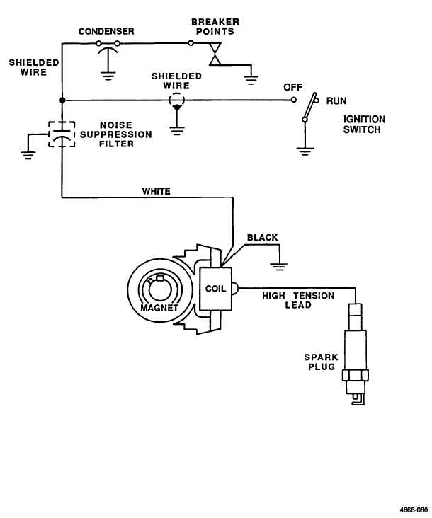
Terminals for coil
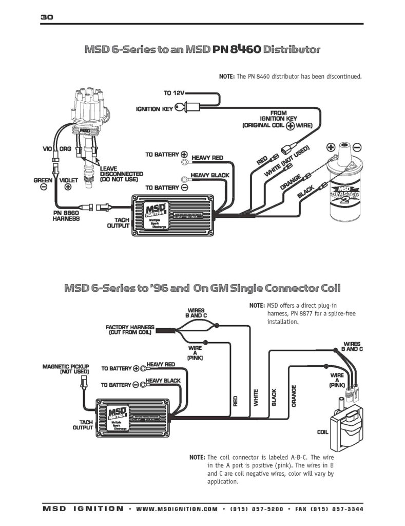
The first step to determine the type of ignition coil is to know the terminology that is used. A basic diagram of the wiring will reveal a variety of connections and terminals. You need to determine the kind of coil you have by testing the voltage on the primary terminal, S1. S1 should also be checked for resistance in order to identify if it’s an A, Type B, or an A coil.
The coil with low tension must be connected to the chassis’ minus. This is the base of the wiring for ignition. The high-tension supply provides the spark plugs with positive electricity directly. It is essential to suppress the coil’s metallic body be connected to its chassis but not essential. The wiring diagram of the ignition will show you how to connect the terminals of either the negative or positive coils. You may find an issue with the ignition coil that is easily identified by scanning it at an auto parts store.
The black-and-white-striped wire from the harness goes to the negative terminal. The negative terminal is served by the black trace joined to the white wire. The black wire goes to the contact breaker. It is possible to remove the black wire from the plug housing using a paper clip in case you are uncertain about the connections. Make sure you verify that the connections haven’t been bent.
Accessory terminals
Ignition wiring diagrams show the various wires used to power the car’s various components. There are typically four color-coded terminals that correspond to each component. Accessories are red, the battery is yellow, and the starter solenoid green. The “IGN terminal is used for starting the car, controlling the wipers and other functions. The diagram illustrates how you can connect ACC or ST terminals, and other.
The terminal BAT is where the battery is. The electrical system won’t start without the battery. A dead battery can make the switch not turn on. You can view your wiring diagram to figure out the location of your car’s batteries. placed. The ignition switch is connected to the battery of your car. The BAT terminal is connected to the battery.
Certain ignition switches have an additional position. This lets users access their outputs from another location without the ignition. Sometimes, customers would like the output of the auxiliary to be used separately from the ignition. You can use the auxiliary input by connecting the connector to the ACC terminal. While this is an excellent feature, there is one important difference. Most ignition switches are set to have an ACC position when the car is in the ACC position, while they’re in the START position when the car is in the IGN position.
Gallery of Mallory Ignition Wiring Diagram
Gallery of Mallory Ignition Wiring Diagram


