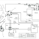
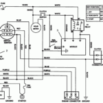
Toro Zero Turn Ignition Switch Wiring Diagram – First, let’s take a look at the different types of terminals on the ignition switch. These terminals are used for the Ignition button, Coil and Accessory. Once we know the purpose of these terminals, we will be able to identify the various parts of the ignition wiring. In addition, we will discuss the function of the Ignition switch and Coil. Then, we will concentrate on the accessories terminals.
Terminals for ignition switch
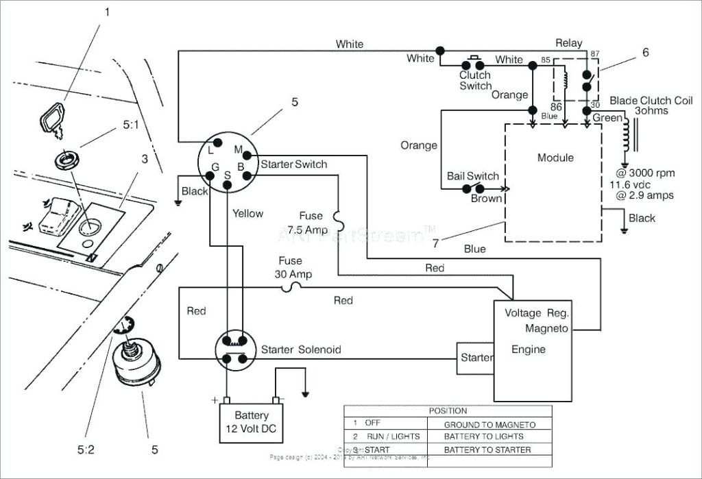
Three switches are found in an ignition switch. Each of these three switches feeds the battery’s voltage to a variety of locations. The first one is used to power the choke by pushing it, while the third switch is used to control the ON/OFF setting. Different manufacturers have different color-coding systems to identify different conductors. We will cover this in another article. OMC utilizes this system. A tachometer adapter is installed on the ignition switch that allows the addition of an Tachometer.
Although many ignition switch terminals don’t come in original form The numbering might not match that of the diagram. To make sure that your wires are properly plugged in to the ignition switch you should check their continuity. A cheap multimeter can help you do this. After you’re happy with the continuity of the wires, you can install the new connector. The wiring loom of the ignition system switch supplied by the manufacturer differs.
It is important to know the differences between the ACC and secondary outputs. The ACC/IGN terminals act as the default connection on the ignition switch. The START/IGN terminals are connected to the stereo or radio. The ignition switch turns the engine of your car ON and off. On older vehicles, the ignition switch terminals are marked with the initials “ACC” as well as “ST” (for individual magnetic wires).
Terminals for Coil
The first step in determining the kind of ignition coil is to comprehend the terminology employed. There are a variety of connections and terminals on the basic wiring diagram for ignition, including two primary, as well as two secondary. Each coil comes with its own operating voltage. To determine which type of coil you’ve got the first step is to check the voltage at S1, which is the primary terminal. S1 must be examined for resistance to determine if the coil is Type A, B, and/or C.
The negative end of the chassis should be connected to the coil’s low-tension end. This is also the ground on the wiring diagram for ignition. The high tension part supplies positively directly to the spark plugs. For suppression purposes, the coil’s body metal is required to be connected to the chassis. It’s not necessary for electrical use. The diagram of the ignition wiring will also demonstrate the connections between the positive and negative coil terminals. There could be an issue with your ignition coil which can be identified by scanning it at an auto parts store.
The black-and-white-striped wire from the harness goes to the negative terminal. The positive terminal also receives the second white wire, which has a black trace. The black wire connects to the contact breaker. To check the connections between the two wires employ a paperclip to lift them off the housing. It is also important to see that the terminals are not bent.
Accessory Terminals
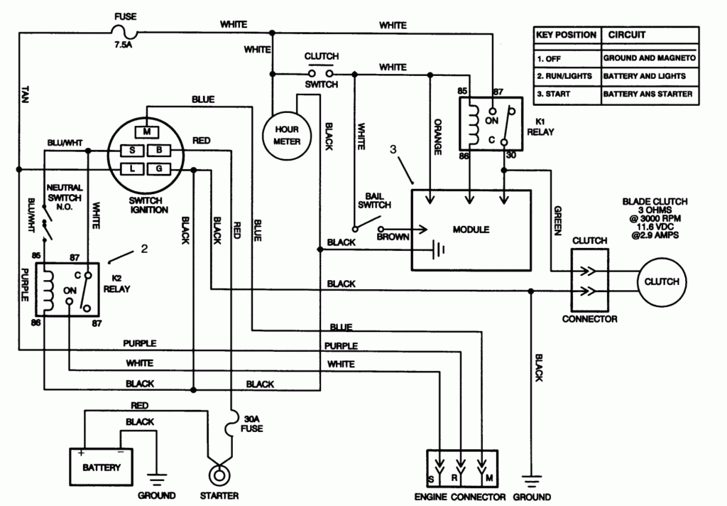
The wiring diagrams of the ignition illustrate the different wires used to power the various components of the vehicle. There are generally four color-coded terminals that correspond to the respective component. To identify accessories, red is for starter solenoid, blue for battery and blue for accessory. The “IGN terminal” is used to run the wipers, along with other operational functions. The following diagram shows how to connect both the ACC terminal and ST terminals to the other components.
The terminal BAT is the connection for the battery. The electrical system can’t begin without the battery. A dead battery could cause the switch to not turn on. If you don’t know where your car’s battery is situated, you can look at the wiring diagram of your car to determine the best way to find it. The accessory terminals in your vehicle connect to the battery as well as the ignition switch. The BAT terminal is connected with the battery.
Some ignition switches feature a separate “accessory” position, where users can manage their outputs without using the ignition. Some customers prefer to make use of an additional output independent of the ignition. Use the secondary output by connecting the connector to the ACC terminal on the switch that has the same color. This is a great convenience feature, but there is one differentiator. Many ignition switches have the ACC position when the car is in ACC mode and a START mode when it is in IGN.
Gallery of Toro Zero Turn Ignition Switch Wiring Diagram
Gallery of Toro Zero Turn Ignition Switch Wiring Diagram


