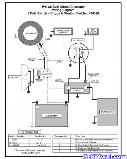
Lawn Mower 5 Prong Ignition Switch Wiring Diagram – We will first look at the various types and purposes of the terminals found on the ignition switches. These include the terminals for the Ignition switch, Coil, and Accessory. Once we’ve established the purpose of these terminals, it is possible to identify the various parts of the ignition wiring. We will also discuss the functions for the Ignition switch and the Coil. After that, we’ll turn our attention to Accessory terminals.
Terminals of ignition switch
The ignition switch has three switches. They feed the voltage of the battery to many different locations. The first switch powers the choke. The second switch controls the ON/OFF switch of the ignition switch. Different manufacturers employ different colors for different conductors. This is described in another article. OMC uses the same method. Connectors can be attached to the ignition switch to connect the digital tachometer.
Although some ignition switch terminals might not be authentic, the numbering of each may not match the diagram. To make sure that the wires are correctly connected to the switch you should check their continuity. A multimeter is a great instrument to verify the continuity. Once you are satisfied with the integrity of the wires, install the new connector. The wiring loom for the ignition switch factory-supplied will be different than the one you have in your vehicle.
It is important to understand the way that ACC outputs and auxiliary outputs function in order to connect them. The ACC/IGN terminals act as the default connections for the ignition switch. The START/IGN connections connect to the stereo or radio. The ignition switch switches the car’s engine ON and off. The terminals on older cars’ ignition switches are labeled by “ACC” as well as ST (for specific magneto wires).
Coil terminals
Understanding the terms is the first step to determining which type of ignition coil you have. A basic ignition wiring diagram will show a variety of connections and terminals, comprising two primary and two secondaries. The operating voltage of each coil differs. Therefore, it is essential to first check the voltage at the S1 (primary terminal). To determine if it is an A, C or B coil, it is recommended to also check the resistance of S1.
The coil’s low-tension end must be connected to the chassis’ positive. It is also the ground in the diagram of ignition wiring. The high-tension part is a positive connection to the sparkplugs. To reduce the noise, the coil’s metal body is required to be connected to the chassis. But, it’s not necessary to electrically connect. The wiring diagram for the ignition will show you how to connect the two terminals of the negative or positive coils. Sometimes, a visit to an auto parts store could detect a defective ignition wire.
The black-and-white-striped wire from the harness goes to the negative terminal. The other white wire is black with a trace on it and it connects to the positive terminal. The black wire is connected to the contactbreaker. To check the connections between the two wires use a paperclip to lift them off the housing. Be sure the terminals do not bend.
Accessory terminals
Diagrams of ignition wiring show the different wires used for powering the various components. Typically there are four colors-coded terminals that are used for each component. To identify accessories, red stands for starter solenoid, yellow is for battery, and blue for accessories. The “IGN” terminal can be used to start the car and operate the wipers and other operating features. The diagram shows how to connect the ACC and ST terminals to the rest of the components.
The terminal BAT holds the battery. The electrical system won’t start without the battery. Additionally the switch isn’t turned on. You can refer to your wiring diagram if uncertain about where the car’s batteries are located. The ignition switch and battery are connected through the accessory terminals. The BAT terminal is connected to the battery.
Certain ignition switches come with an “accessory” setting that allows users to regulate their outputs without needing to utilize the ignition. Sometimes, customers want to utilize an auxiliary output that is separate from the ignition. For the auxiliary output to be used, wire the connector to the same shade as the ignition. Then connect it with the ACC end of the switch. While this is an excellent feature, there’s something you should know. The majority of ignition switches are set to be in an ACC position when the car is in the ACC position, while they’re in the START position when the car is in the IGN position.
Gallery of Lawn Mower 5 Prong Ignition Switch Wiring Diagram
Gallery of Lawn Mower 5 Prong Ignition Switch Wiring Diagram


