Caterpillar Ignition Switch Wiring Diagram – First, we will look at the various types of terminals that are used on the ignition switch. These terminals include the Ignition switch as well as the Coil along with the Accessory. Once we have established what these kinds of terminals are used for then we can identify the different parts of the Caterpillar Ignition Switch Wiring Diagram. We’ll also discuss the functions as well as the Coil. Then we’ll discuss the Accessory Terminals.
Terminals for ignition switch
An ignition switch has three switches. They feed the voltage of the battery to different places. The first switch provides power to the choke and the third switch toggles the on/off status of the ignition switch. Different manufacturers use various color codes for the various conductors. This is explained in another article. OMC uses the same method. The ignition switch also includes an option to connect an tachometer.
Although some ignition switch terminals could not be original, the numbers of each one might not be in line with the diagram. Examine the integrity of the wires first to ensure that they’re connected correctly to the ignition switch. You can check this using a simple multimeter. After you have verified the integrity of the wires you can connect the connector. If your car is equipped with an original factory-supplied ignition switch (or wiring loom), the wiring loom will differ from that in the car.
First, understand the differences between ACC and auxiliary outputs. The ACC and IGN terminals are the default connections for the ignition switch. the START and IGN terminals are the primary connections to the stereo and radio. The ignition switch acts as the engine’s on/off button. The terminals on older cars ignition switches are marked by “ACC” and ST (for the individual magneto wires).
Terminals for coil
To figure out the type of ignition coil you need to know the step is to learn the terminology. A basic diagram of the wiring will reveal a variety of connections and terminals. You need to determine the type of coil that you own by examining the voltage at the primary terminal S1. S1 must be examined for resistance to identify if the coil belongs to type A, B or C.
The low-tension side of the coil should be connected to the chassis’ negative. This is the ground on the wiring diagram for ignition. The high-tension part supplies the spark plugs with positive. The body of the coil has to connect to the chassis to prevent it from being smothered however it isn’t electrically essential. The wiring diagram for ignition will also show the connection of the positive coil terminals. Sometimes, a check at an auto parts store could identify a problem with the ignition wire.
The black-and-white-striped wire from the harness goes to the negative terminal. The other white wire is black-colored and goes to the negative terminal. The black wire is connected to the contactbreaker. If you’re unsure of the connections of the twowires, use the clip of a paperclip to remove them from the housing of the plug. Check that the terminals aren’t bent.
Accessory terminals
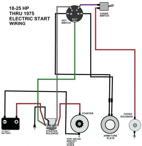
Diagrams of ignition wiring show the various wires utilized to power the vehicle’s various components. In general, there are four different color-coded terminals for each component. To identify accessories, red is the starter solenoid’s color, yellow is for battery, and blue for accessory. The “IGN” terminal can be utilized to turn on the car, turn on the wipers and other functions. This diagram demonstrates how to connect ACC and ST terminals with the rest of components.
The battery is attached to the terminal whose name is BAT. Without the battery, the electrical system does not start. A dead battery could cause the switch to not come on. If you’re not sure the exact location where the battery in your car is situated, review your wiring diagram to see how to locate it. The accessory terminals in your car are connected to the ignition switch as well as the battery. The BAT Terminal is connected to the battery.
Some ignition switches offer an additional “accessory position” which allows users to adjust their outputs independently of the ignition. Some customers prefer to make use of an additional output that is not connected to the ignition. The auxiliary output could be utilized to connect the connector with the same color as your ignition and attaching it to the ACC terminal of the switch. Although this is a fantastic feature, there’s something you should know. The majority of ignition switches have an ACC position if the car is in the ACC however, they will be in the START position when the vehicle is in IGN.
Gallery of Caterpillar Ignition Switch Wiring Diagram
Gallery of Caterpillar Ignition Switch Wiring Diagram


