Yamaha Ignition Switch Wiring Diagram – Let’s first examine the different types and purposes of the terminals in the ignition switches. These terminals comprise the Ignition switch and Coil as well as the Accessory. Once we’ve determined the function of the terminals it is possible to determine the various components of the ignition wiring. Then, we will discuss the functions as well as the Coil. The next step is to focus to the accessory terminals.
Terminals for ignition switch
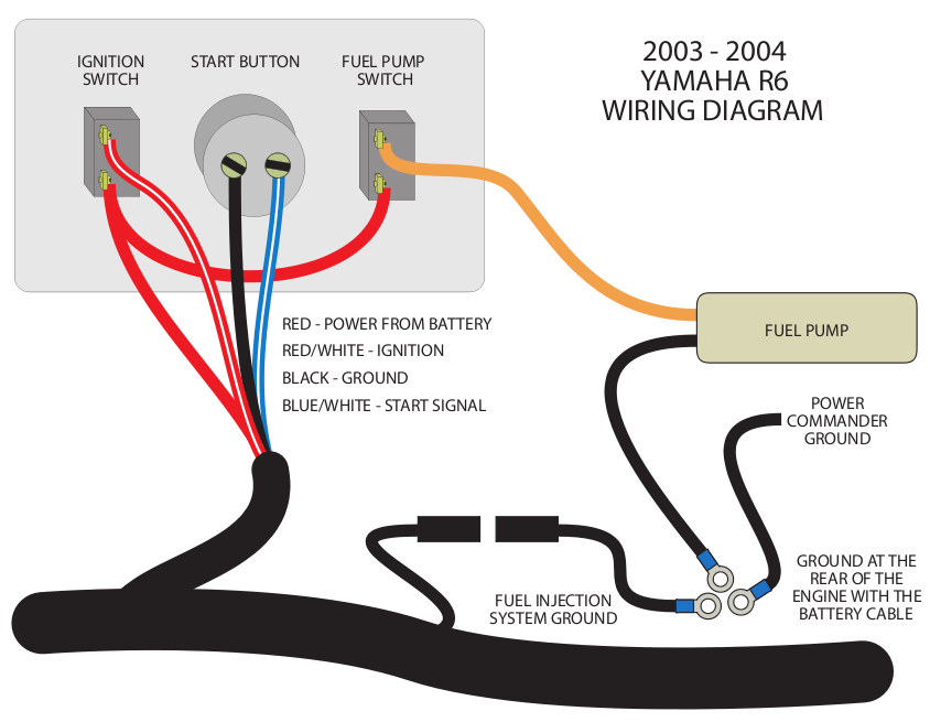
An ignition switch is comprised of three switches. They feed the voltage of the battery to different locations. The ON/OFF setting of the ignition switch is controlled by the second switch, which supplies power to the choke when it’s pulled. Different manufacturers have their own color-coding system for the various conductors, that is described in a separate article. OMC follows the same system. A connector is also included inside the ignition switch for connecting a to a tachometer.
While many ignition switch terminals might not be authentic, the numbering of the terminals may not match the diagram. To make sure that your wires are properly plugged in to the ignition switch, you should check their continuity. This can be checked using a cheap multimeter. When you’re satisfied with the integrity of the wires, then you’ll be able install the new connector. If your car has an installed ignition switch, the wiring diagram will differ.
It is important to know the differences between ACC and secondary outputs. The ACC terminals as well as the IGN terminals are the standard connections for the ignition switch. The START and IGN connections are the most important connections for stereo and radio. The ignition switch is responsible for turning the engine of your car on and off. In older vehicles the terminals of the ignition switch are identified with the letters “ACC” as well as “ST” (for the individual magnetic wires).
Terminals for coil
The terminology used to determine the type and model of an ignition coil is the primary thing. An understanding of the basic wiring diagram for ignition will reveal a variety of connections and terminals. The coils come with a distinct operating voltage, and the first step to determine which one you’ve got is to check the voltage on S1, the primary terminal. S1 should also undergo resistance tests to determine if it’s a Type A or B coil.
The chassis’ negative end should be connected to to the coil’s lower-tension end. This is also the ground in the diagram of ignition wiring. The high-tension supply supplies positively directly to spark plugs. It is essential for the purpose of suppression that the body of the coil’s metal be connected to its chassis however it isn’t essential. The wiring diagram of the ignition will demonstrate how to connect the terminals of the negative or positive coils. It is possible to find an issue with your ignition coil that is easily identified by scanning it at an auto parts store.
The black-and-white-striped wire from the harness goes to the negative terminal. The positive terminal also receives the white wire that is black in its trace. The black wire connects to the contact breaker. You can check the connections with a pencil to remove the wires from the housing. Be sure that you don’t bend the connectors.
Accessory terminals
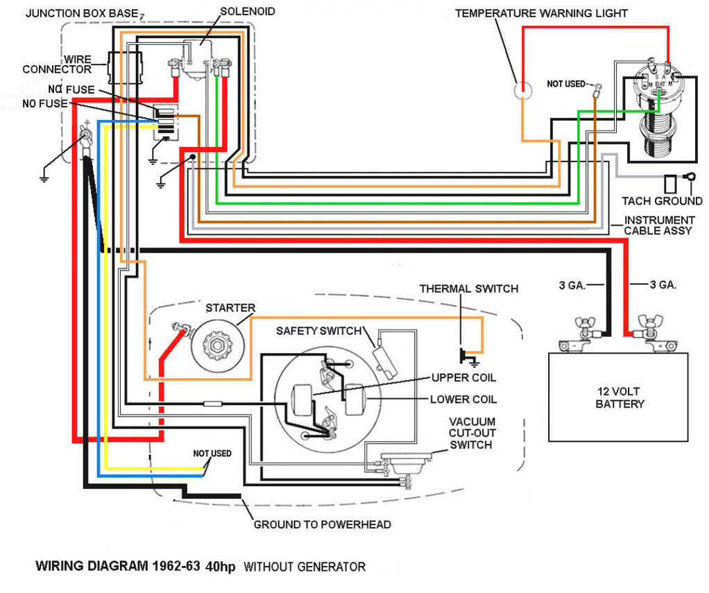
The ignition wiring diagrams illustrate the different wires that power the various components of the car. There are usually four different color-coded terminals to each component. For accessories, red is the starter solenoid’s color, yellow for battery, and blue is for accessories. The “IGN” terminal can be utilized to turn on the car, control the wipers and other features. This diagram demonstrates how to connect ACC and ST terminals to the rest of components.
The terminal BAT holds the battery. The battery is vital for the electrical system to get started. In addition, the switch will not start. It is possible to view the wiring diagram of your car to see where your car’s batteries are situated. The accessory terminals on your car connect to the battery and the ignition switch. The BAT Terminal is connected to the Battery.
Certain ignition switches have an accessory position. This lets users connect their outputs to a different location without the ignition. Sometimes, customers would like the auxiliary output to be operated independently of the ignition. In order to use the auxiliary output, wire the connector using identical colors to the ignition and connect it to the ACC terminal on the switch. This feature is convenient however it does have one significant difference. A majority of ignition switches feature the ACC position when your car is in the ACC mode, and a START position when you are in IGN.
Gallery of Yamaha Ignition Switch Wiring Diagram
Gallery of Yamaha Ignition Switch Wiring Diagram


