Cdi Ignition Wiring Diagram – First, we will look at the different types of terminals found on the ignition switch. These terminals comprise the Ignition switch as well as the Coil and the Accessory. After we’ve identified the purpose of these terminals, we can determine the various components of the ignition wiring. We will also discuss the functions for the Ignition switch as well as the Coil. Then we’ll move on to the Accessory Terminals.
Terminals for the ignition switch
The ignition switch consists of three switches. They are the ones that supply the battery’s power to various places. The first one supplies power to the choke when it is pushed. The third is the ignition switch’s ON/OFF position. Different manufacturers have their own color-coding system for the different conductors, which is explained in a different article. OMC utilizes this system. A connector is also included in the ignition switch to allow attaching a Tachometer.
Even though most ignition switch terminals do not have an original number, they might have a different number. Before plugging in the ignition switch, be sure to test the continuity. This can be done using an inexpensive multimeter. Once you’re satisfied with the continuity it’s time to connect the new connector. If you are using a factory-supplied ignition switch, the wiring loom is distinct from the one that is in your car.
It is important to understand the way that ACC outputs and auxiliary outputs work in order to connect them. The ACC and IGN terminals are the default connections on your ignition switch. the START and IGN terminals are the principal connections for stereo and radio. The ignition switch’s function is to turn the car’s engines on and off. The terminals for the ignition switch on older vehicles are marked with the initials “ACC” as well as “ST” (for the individual magneto wires).
Terminals for Coil
The first step in determining the type of ignition coil is to know the terminology that is used. In a basic ignition wiring diagram you’ll see several different terminals and connections, including two primary and two secondary. It is essential to identify the type of coil that you own by examining the voltage at the primary terminal S1. S1 must be tested for resistance in order to determine if the coil is Type A, B, and/or C.
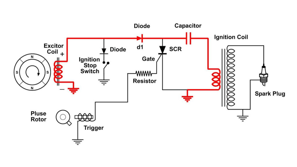
The coil’s low-tension component is to be connected to the chassis positive. This is what you find in the diagram of wiring. The high-tension side delivers positively direct to the spark plugs. To prevent noise, the coil’s metal body must be connected to chassis. It is not necessary to electrically connect. The wiring diagram for the ignition will show you how to connect the terminals of either the positive and negative coils. Sometimes, a malfunctioning ignition coil can be identified with a scan at an auto parts shop.
The black-and-white-striped wire from the harness goes to the negative terminal. The positive terminal receives the other white wire and the trace in black. The black wire is connected to the contact breaker. To check the wires’ connections use a paperclip to lift them out of the housing. Make sure that the terminals aren’t bent.
Accessory terminals
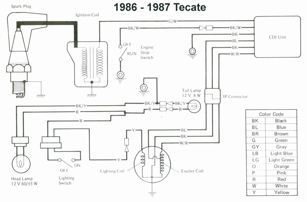
Diagrams of ignition wiring depict the wiring used to supply power to different parts of the car. There are generally four colors-coded terminus of each part. Red stands for accessories, yellow represents the battery, and green for the solenoid for starters. The “IGN” terminal is used to start the car, controlling the wipers, and for other functions. The following diagram illustrates how to connect the ACC terminal and ST terminals to other components.
The terminal BAT connects the battery to the charger. The electrical system can’t begin without the battery. Additionally, the switch will not start without the battery. If you’re not sure of the location of your car’s battery situated, review your wiring diagram to figure out where it is. The accessory terminals in your car connect to the ignition switch and the battery. The BAT terminal is connected with the battery.
Some ignition switches feature the “accessory” setting that permits users to control their outputs , without needing to utilize the ignition. Sometimes, customers would like the output of the auxiliary to be used independently from the ignition. Use the additional output by connecting the connector to the ACC terminal on the switch that has the same color. This is a useful feature, however there’s one important difference. A lot of ignition switches can be configured to be in an ACC position when the vehicle has been moved into the ACC position. They’ll also be in the START mode after the vehicle has been entered the IGN position.
Gallery of Cdi Ignition Wiring Diagram
Gallery of Cdi Ignition Wiring Diagram


