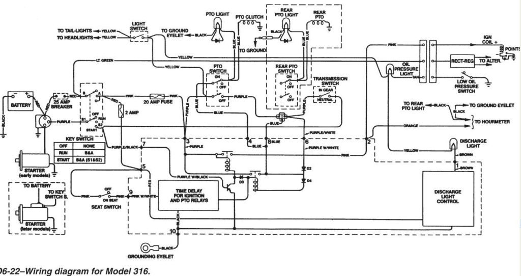
John Deere 316 Ignition Switch Wiring Diagram – The first step is to look at the various types of terminals that are used on the ignition switch. These are the terminals that connect the Ignition, Coil, or Accessory. After we’ve identified the purpose of these terminals and what they do, we can then be able to identify the various parts of the ignition wiring. We’ll also go over what functions are available for the Ignition switch and the Coil. Then, we will concentrate on the accessories terminals.
Terminals for the ignition switch

Three switches can be found on an ignition switch. Each of these switches feeds the battery’s voltage to several different locations. The first switch provides power to the choke, and the third switch toggles the ON/OFF state of the switch. Different manufacturers have different color-coding systems to identify different conductors. We’ll discuss this in another article. OMC follows this scheme. The ignition switch also includes a connector for adding an Tachometer.
Even though some of the ignition switch terminals may not be authentic, the numbering of each one might not match the diagram. Examine the electrical continuity first to ensure that they’re connected correctly to the ignition switch. You can check this using a simple multimeter. After you have verified the integrity of the wires you can then install the connector. If your vehicle has an ignition switch that is installed, the wiring diagram will differ.
It is important to understand the way that ACC outputs and the auxiliary outputs function in order to join them. The ACC and IGN terminals are the default connection on the ignition switch. the START and IGN terminals are the main connections for the radio and stereo. The ignition switch is the one that controls the engine of your car. On older cars the terminals of the ignition switch are marked with the letters “ACC” and “ST” (for individual magnetic wires).
Terminals for coil
Understanding the terminology is the first step in finding out what kind of ignition coil you have. The basic ignition wiring diagram depicts various connections and terminals. There are two primary and secondary connections. Each coil is operating at a certain voltage. The first step to determine which kind you’re dealing with is to test the voltage at S1 or the primary terminal. S1 must be checked for resistance to determine if the coil is type A, B or C.
The coil’s low-tension side must be connected with the chassis’ positive. This is the base of the wiring for ignition. The high tension side supplies positive power directly to the spark plugs. For suppression purposes, the coil’s metal body must be connected to the chassis. But, it’s not necessary to electrically connect. The diagram of the ignition wiring will also indicate the connections of the positive coil terminals. You may find an issue with the ignition coil that is easily identified by looking it up at an auto parts retailer.
The black-and-white-striped wire from the harness goes to the negative terminal. The other white wire has a black color and connects to the terminal opposite. The black wire is connected to the contactbreaker. If you’re unsure of the connections between both, you can use a paper clip to remove them from the housing of the plug. Be sure to ensure that the terminals have not been bent.
Accessory terminals
The ignition wiring diagrams show the various wires utilized to power different components. There are usually four colored terminus lines for each component. For accessories, red stands the starter solenoid’s color, yellow is for battery, and blue for accessories. The “IGN terminal is used to start the car, operating the wipers and various other functions. The diagram below shows how to connect both the ACC terminal and ST terminals to various components.
The battery is connected to the terminal named BAT. Without the battery, the electrical system does not get started. The switch won’t be able to turn on if the battery isn’t present. To find your car’s battery look over your wiring diagram. The ignition switch and the battery are connected by the accessory terminals. The BAT terminal is connected to the battery.
Some ignition switches are equipped with an accessory position. This lets users access their outputs from a different location without the ignition. Some customers may prefer to utilize the auxiliary output in addition to the ignition. The auxiliary output could be used by wiring the connector in the same color as your ignition and connecting it to the ACC terminal of the switch. This is an excellent feature, however there’s an important distinction. The majority of ignition switches have an ACC position when the vehicle is in the ACC, but they will be at the START position if the vehicle is IGN.
Gallery of John Deere 316 Ignition Switch Wiring Diagram
Gallery of John Deere 316 Ignition Switch Wiring Diagram


