Durite Ignition Switch Wiring Diagram – We will first look at the various types of terminals for the ignition switch. These terminals comprise the Ignition switch, the Coil and the Accessory. Once we know which terminals are used then we can determine the various components of the Durite Ignition Switch Wiring Diagram. We’ll also discuss the functions of both the Ignition Switch and Coil. After that, we’ll turn our attention to the Accessory terminals.
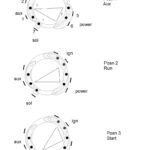
Terminals of ignition switch

An ignition switch contains three different switches that direct the battery’s current to various locations. The first one supplies power to the choke when pushed, and the second is the switch that controls the ignition’s ON/OFF positions. Different manufacturers use their own color-coding systems for different conductors which is documented in another article. OMC follows this scheme. An adapter is included on the ignition switch to allow the addition of an tonometer.
Although the majority of ignition switch terminals can be duplicated, the numbers may not match the diagram. Examine the electrical continuity first to make sure they are correctly plugged in the ignition switch. A multimeter is a good instrument to verify the continuity. When you are happy with the continuity of the wires, you can connect the new connector. The wiring loom used in the ignition system switch supplied by the manufacturer differs.
Knowing how the ACC outputs are connected to the auxiliary outputs in your car is vital. The ACC and IGN connectors are the standard connections for your ignition switch. The START, IGN, and ACC terminals are primary connections for radios or stereo, the START/IGN terminals are the main ones. The ignition switch’s function is to turn the car’s engines on and off. Older vehicles have ignition switch terminals labeled “ACC” or “ST” (for individual magnetowires).
Coil terminals
Understanding the terminology is the initial step towards knowing what type of ignition coil you’ve got. In a typical ignition wiring diagram you’ll see various connections and terminals, which include two primary and two secondary. It is essential to identify the kind of coil you own by examining the voltage on the primary terminal S1. To determine whether it’s a Type A, C or B coil you should also test S1’s resistance.
The negative end of the chassis end should be connected to connect to the coil’s lower-tension end. This is the ground of the ignition wiring. The high tension part supplies positive directly the spark plugs. For suppression purposes, the coil’s body metal is required to be connected to the chassis. This is not necessary for electrical use. The wiring diagram will illustrate the connection between the positive and negative coils. In certain instances it is recommended to conduct a scan at your local auto parts shop will help identify malfunctioning ignition coils.
The black-and-white-striped wire from the harness goes to the negative terminal. The white wire has a black color and goes to the terminal opposite. The black wire connects with the contact breaker. It is possible to remove the black wire from the plug housing by using a paperclip if you are unsure about the connections. Make sure you don’t bend the connectors.
Accessory Terminals

The ignition wiring diagrams illustrate the various wires utilized to power the vehicle’s various parts. There are typically four colors of terminals connected to each part. Accessories are red while the battery is yellow and the starter solenoid green. The “IGN terminal allows you to start the car, control the wipers, and any other features that operate. The diagram shows the connections between the ACC- and ST terminals.
The battery is attached to the terminal named BAT. The electrical system will not start without the battery. The switch will not turn on if there is no battery there. To locate your car’s battery look over your wiring diagram. The accessory terminals in your car connect to the battery as well as the ignition switch. The BAT terminal connects to the battery.
Certain ignition switches have an independent “accessory” location, which allows users can manage their outputs without using the ignition. Users may wish to use the auxiliary output separately from the ignition. You can utilize the additional input by connecting it to the ACC terminal. While this is an excellent option, there’s an significant difference. Most ignition switches are configured to be in an ACC position when the car is in the ACC position, but they’re set to the START position when the vehicle is in the IGN position.
Gallery of Durite Ignition Switch Wiring Diagram
Gallery of Durite Ignition Switch Wiring Diagram


