Craftsman Lawn Tractor Ignition Wiring Diagram – First, we will take a look at the various kinds of terminals that are found on the ignition switch. These include the terminals that are for the Ignition switch, Coil, and Accessory. After we’ve established what these types of terminals are, we will proceed to identify the different parts of the Craftsman Lawn Tractor Ignition Wiring Diagram. Then, we will discuss the functions as well as the Coil. We’ll then turn our attention to the accessory terminals.
Terminals for the ignition switch
The ignition switch has three switches. They supply the voltage of the battery to different places. The first switch is the one that supplies power to the choke and the third switch toggles the state of the switch. Different manufacturers have distinct colors-coding systems to match the conductors. OMC utilizes this method. A connector is also included in the ignition switch for attaching an to a tachometer.
Although some ignition switch terminals may not be authentic, the numbering of each one might not be in line with the diagram. You should first check the electrical continuity to determine if they’re connected to the ignition switch in the correct way. A multimeter is an excellent tool to check the continuity. Once you’re satisfied with the continuity, you can place the new connector. If your car has an installed ignition switch the wiring diagram will differ.
For connecting the ACC outputs to the auxiliary outputs on your car, you need to understand the way these two connections function. The ACC and IGN terminals are the default connections on your ignition switch, and the START and IGN terminals are the main connections to the stereo and radio. The ignition switch is the one that turns the car’s engine on and off. In older vehicles the ignition switch’s terminals are identified with the alphabets “ACC” and “ST” (for the individual magnet wires).
Terminals for coil
Understanding the terminology utilized is the initial step in determining what kind of ignition coil you need. A basic ignition wiring diagram will show a variety of connections and terminals, which include two primary terminals and two secondaries. Each coil is equipped with a distinct operating voltage. To determine what kind of coil you own the first step is to check the voltage at the S1 primary terminal. To determine if it is a Type A, C or B coil, you must also check the resistance of S1.
The chassis’ negative must be connected to to the coil’s lower-tension end. This is the base of the ignition wiring. The high-tension part is a positive connection to the sparkplugs. The aluminum body of the coil needs to be connected to the chassis to prevent it from being smothered however it’s not electrically required. You will also see the connections of the negative and positive coil’s terminals on an diagram of the ignition wiring. Sometimes, a defective ignition coil can be detected through a scan performed in an auto parts shop.
The black-and-white-striped wire from the harness goes to the negative terminal. The terminal that is negative is served by the trace in black that’s joined to the white wire. The black wire connects with the contact breaker. You can examine the connections with a pencil to remove the wires of the housing. Be sure that you don’t bend the connectors.
Accessory terminals
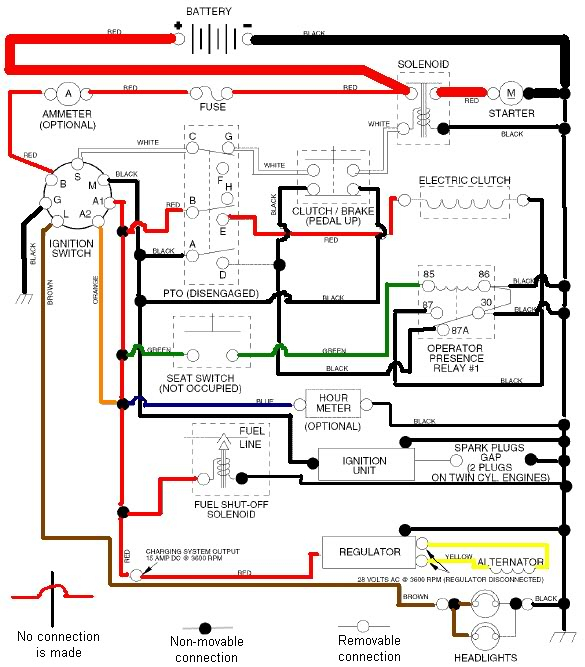
Diagrams of ignition wiring show the wires used in the vehicle’s power supply. There are typically four color-coded terminals to each component. Red is used for accessories and yellow is for the battery, and green is the starter solenoid. The “IGN” terminal can be used to start the vehicle and control the wipers as well as other operational features. The diagram illustrates the connection to the ACCas well as ST terminals.
The terminal known as BAT is the location where the battery is. The electrical system won’t start if the battery isn’t connected. A dead battery can make the switch not turn on. If you’re not sure of the location of your car’s battery situated, review the wiring diagram of your car to determine how to locate it. The accessory terminals of your vehicle connect to the battery as well as the ignition switch. The BAT Terminal is connected to the battery.
Certain ignition switches have an additional position. This lets users connect their outputs to a different place without having to turn on the ignition. Sometimes, users want to make use of an additional output that is independent of the ignition. You can use the additional output by connecting the connector to the ACC terminal on the switch with the same colors. Although this is a fantastic option, there’s a thing to be aware of. Most ignition switches come with an ACC position when your vehicle is in ACC mode and a START position when you are in IGN.
Gallery of Craftsman Lawn Tractor Ignition Wiring Diagram
Gallery of Craftsman Lawn Tractor Ignition Wiring Diagram


