Wiring Diagram For Evinrude Ignition Switch – First, we will take a look at the various kinds of terminals on the ignition switch. They include terminals for Coil, Ignition Switch, and Accessory. When we have a clear understanding of the purpose of each type of terminal, we can then identify the various components of the ignition wiring. We’ll also discuss the functions of the Ignition switch, as well as the Coil. We’ll then turn our attention to the accessory terminals.
Terminals for ignition switch
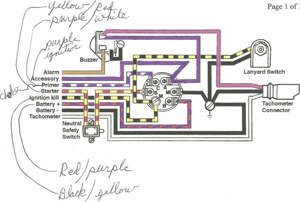
An ignition switch is comprised of three switches. They supply the battery’s voltage to different locations. The first switch is the one that supplies the choke with power, while the second toggles the on/off status of the ignition switch. Different manufacturers employ various color codes for the different conductors. This is described in a different article. OMC uses this system. The ignition switch comes with a connector for adding the Tachometer.
Although the majority of ignition switch terminals can be duplicated, the number may not be in line with the diagram. To make sure that your wires are plugged in to the ignition switch, you should check their continuity. This can be accomplished using a cheap multimeter. After you have verified the continuity of the wires you are able to connect the connector. If your vehicle has an installed ignition switch the wiring diagram may differ.
It is important to know the differences between the ACC and auxiliary outputs. The ACC and IGN terminals are the default connection on the ignition switch. the START and IGN terminals are the principal connections for the radio and stereo. The ignition switch turns the engine of your car ON and off. In older vehicles, the ignition switch terminals are marked with the alphabets “ACC” and “ST” (for distinct magnetic wires).
Terminals for coil
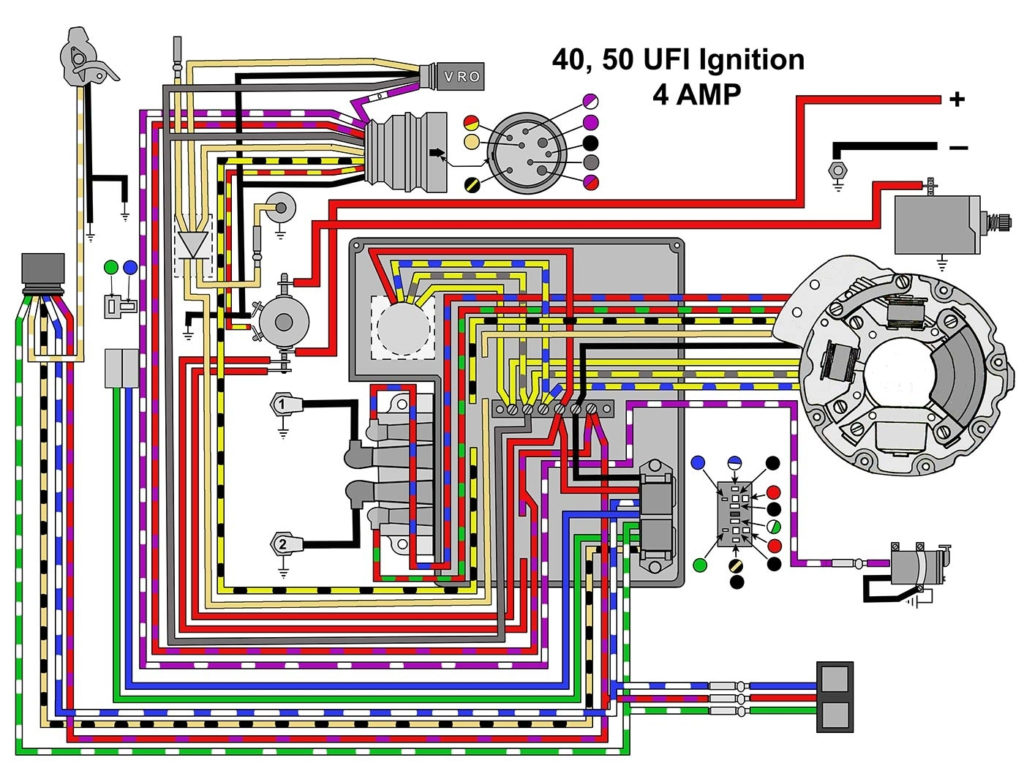
Understanding the terminology is the initial step in finding out what kind of ignition coil you own. An ignition wiring diagram will show a variety of terminals and connections, which include two primary terminals and two secondary. Each coil has an operating voltage. The first step to determine the kind you’re using is to examine the voltage on S1, or the primary terminal. S1 should be checked for resistance to identify if the coil belongs to Type A, B, and/or C.
The coil’s low-tension end must be connected to the chassis’ positive. This is the ground of the wiring for ignition. The high-tension component provides the spark plugs with positive. For suppression purposes the body of the coil is required to be connected to the chassis. It is not necessary to electrically connect. It is also possible to see the connections of the positive and negative coil terminals on the diagram of the ignition wiring. Sometimes, an inspection at an auto part store can identify a problem with the ignition wire.
The black-and-white-striped wire from the harness goes to the negative terminal. The white wire also is black with a trace, and it goes to the positive terminal. The black wire is connected to the contact breaker. You can take the black wire from the plug housing using a paper clip If you’re unsure of the connections. You should also check to see that the terminals aren’t bent.
Accessory terminals
The wiring diagrams of the ignition illustrate the various wires that provide power to the various parts of the vehicle. There are typically four different colored terminus lines for each component. The accessories are red while the battery is yellow and the starter solenoid green. The “IGN” terminal can be used to start the car and operate the wipers and other operating functions. This diagram demonstrates how to connect ACC and ST terminals with the rest of components.
The terminal BAT connects the battery to the charger. The battery is essential to allow the electrical system to get started. The switch will not turn off if the battery isn’t present. A wiring diagram can tell you the location of your car’s battery. The ignition switch is connected to the car’s battery. The BAT connector is connected to your battery.
Some ignition switches come with an additional “accessory position” that allows users to alter their outputs without the ignition. Sometimes, customers want to make use of the auxiliary output separately from the ignition. Make use of the secondary output by connecting the connector to an ACC terminal on the switch with the same colors. This is an excellent option, but there’s an important distinction. Many ignition switches can be configured to be in an ACC location when the car has moved into the ACC position. They also will be in the START position after the vehicle has been entered the IGN position.
Gallery of Wiring Diagram For Evinrude Ignition Switch
Gallery of Wiring Diagram For Evinrude Ignition Switch


