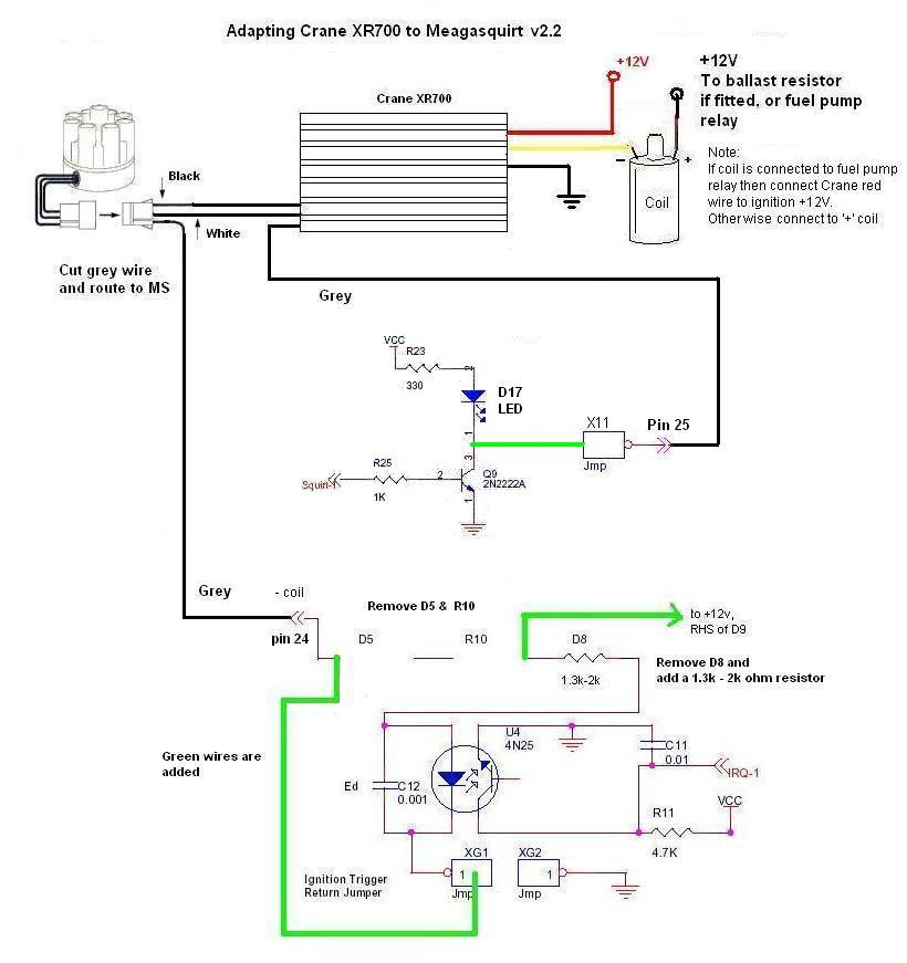
Crane Cam Fireball Xr700 Ignition Wiring Diagram – We will first examine the different types of terminals that are used on the ignition switch. These include the terminals that are for the Ignition switch, Coil, and Accessory. Once we’ve established the purpose of these terminals, we will be able to determine the various components of the ignition wiring. We will also talk about the functions and the Coil. Following that, we’ll shift our attention to Accessory terminals.
Terminals of ignition switch
An ignition switch has three switches. They supply the voltage of the battery to many different places. The ON/OFF setting of the ignition switch is controlled by the third switch, which delivers the choke with power when it’s pushed. Different manufacturers have different color-coding schemes for different conductors. We’ll discuss this in a separate article. OMC utilizes this method. A connector is also included inside the ignition switch to allow attaching a Tachometer.
While some ignition switch terminals don’t come in original form The numbering might not be in line with the diagram. To ensure that the wires are correctly connected to the ignition switch, you must verify their continuity. A multimeter is an excellent instrument to verify the continuity. Once you are satisfied with the integrity of the wires, it is time to install the new connector. The wiring loom used in an ignition system switch that is supplied by the manufacturer is distinct.
It is important to know the differences between ACC and secondary outputs. The ACC/IGN connections function as the default connections on the ignition switch. The START/IGN connections connect to the radio or stereo. The ignition switch’s function is for turning the car’s engine on and off. The terminals on older cars’ ignition switches are labeled with “ACC” and ST (for the individual magneto wires).
Terminals for coil
Understanding the terminology is the initial step towards determining which type of ignition coil you own. An ignition wiring diagram will reveal a variety of terminals and connections comprising two primary and two secondary. The coils are equipped with a particular operating voltage. The initial step in determining which type you have will involve testing the voltage of S1 the main terminal. You should also test S1 for resistance in order to identify if it’s a Type A or B coil.
The coil’s low-tension component must be connected with the chassis’ positive. This is the ground in the wiring diagram for ignition. The high tension side provides positively directly to the spark plugs. To prevent noise the coil’s metal body must be connected to the chassis. This is not necessary for electrical use. The diagram for the ignition wiring will also reveal how to connect the negative and positive coil terminals. It is possible to find an issue with the ignition coil that can be easily diagnosed by scanning it in an auto parts retailer.
The black-and-white-striped wire from the harness goes to the negative terminal. The positive terminal receives the other white wire, which has the trace in black. The black wire goes to the contact breaker. You can remove the black wire from the housing of the plug by using a paperclip in case you are uncertain about the connections. Also, see that the terminals aren’t bent.
Accessory terminals
Diagrams of ignition wiring show the various wires that are used for powering the different components. Each part has four distinct color-coded connections. The red color is for accessories, yellow is the battery, and green the starter solenoid. The “IGN terminal lets you start your car, operate the wipers, and any other operation features. The below diagram shows how to connect the ACC terminal as well as the ST terminals to other components.
The terminal BAT connects the battery to the charger. Without the battery the electrical system can not begin. The switch won’t turn on if there is no battery there. If you’re not sure of where your car’s battery is situated, you can examine your wiring diagram to see where it is. The ignition switch is connected to the battery of your car. The BAT connector connects to your battery.
Some ignition switches offer the option of an “accessory position” that allows users to modify their outputs independent of the ignition. Sometimes, customers wish to use the auxiliary output separately from the ignition. You can utilize the additional input by connecting it to the ACC terminal. This is a convenient feature however, it does have one key differentiator. The majority of ignition switches are set to be in an ACC position when the car is in the ACC position, whereas they’re in the START position when the car is in the IGN position.
Gallery of Crane Cam Fireball Xr700 Ignition Wiring Diagram
Gallery of Crane Cam Fireball Xr700 Ignition Wiring Diagram


