Murray Lawn Mower Ignition Switch Wiring Diagram – The first step is to take a look at the different kinds of terminals for the ignition switch. These are the terminals that connect the Ignition, Coil, or Accessory. Once we have established what these types of terminals are used for then we can identify the different parts of the Murray Lawn Mower Ignition Switch Wiring Diagram. In addition, we will discuss the roles of both the Ignition Switch and Coil. We’ll then turn our attention to the accessory terminals.
Terminals for ignition switch
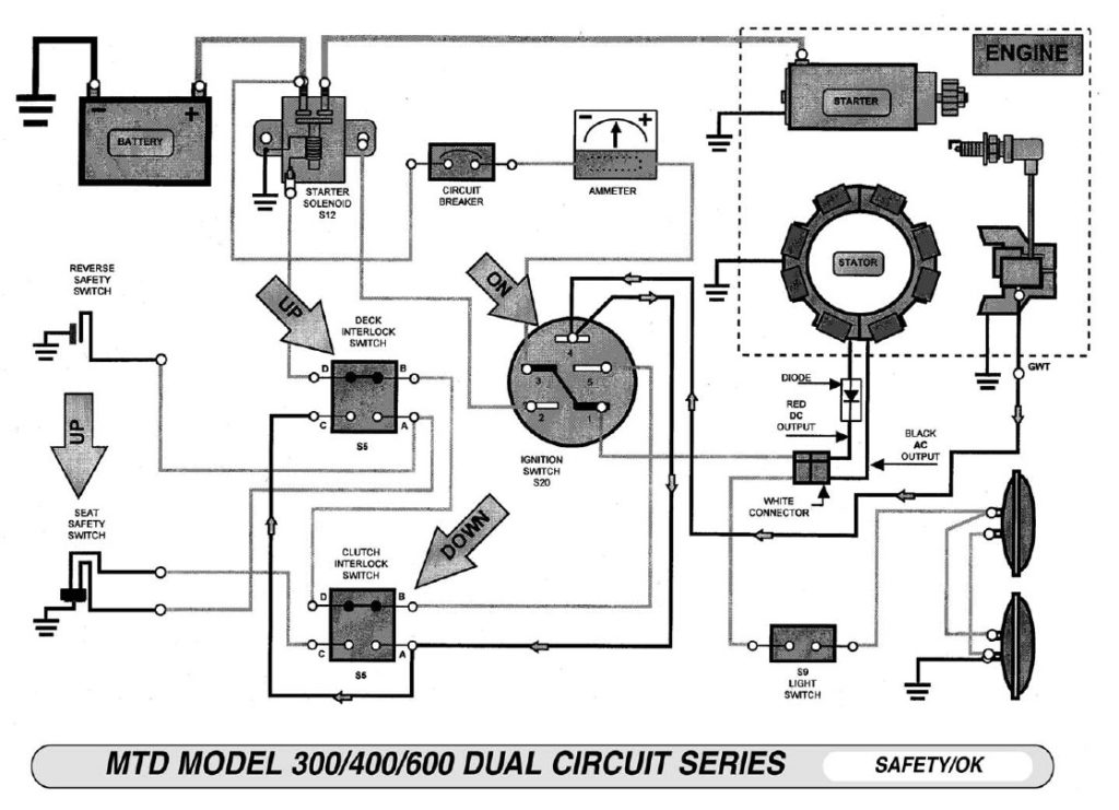
There are three different switches on the ignition switch, and they provide the battery’s voltage to various locations. The first switch is the one that supplies the choke with power, while the second switch controls the ON/OFF state of the switch. Different manufacturers employ various color codes for the various conductors. This is discussed in another article. OMC utilizes the same system. There is a connector in the ignition switch to allow connecting a Tachometer.
Although the majority of ignition switch terminals do not have an original number, they may be equipped with a different number. The first step is to check the continuity of all wires to make sure they’re properly plugged into the ignition switches. A cheap multimeter can aid in this. When you’re happy with the connection it’s time to connect the new connector. If you are using an ignition switch supplied by the manufacturer, the wiring loom is different from the one in your car.
First, understand the differences between the ACC and secondary outputs. The ACC terminals as well as the IGN terminals function as the standard connections for the ignition switch. The START and IGN connections are the primary connections for stereo and radio. The ignition switch is accountable for turning the car’s engine on and off. The ignition switch terminals on older cars are labeled with the initials “ACC” as well as “ST” (for individual magneto wires).
Terminals for coil
The first step to determine the kind of ignition coil is to comprehend the terminology that is used. A basic ignition wiring diagram will reveal a variety of terminals and connections, which include two primary terminals and two secondaries. It is essential to identify the kind of coil you own by examining the voltage on the primary terminal, S1. It is also recommended to examine S1 for resistance to identify if it’s a Type A B, C, or coil.
The coil with low tension must be connected to the chassis’s minus. It is also the ground for an ignition wiring diagram. The high tension part supplies positively directly to the spark plugs. The body of the coil has to be connected to the chassis for suppression purposes, but it is not electrically required. The ignition wiring diagram will also indicate the connection of the positive coil terminals. In some cases, you’ll find that a malfunctioned ignition coil is identified by a scan at an auto parts shop.
The black-and-white-striped wire from the harness goes to the negative terminal. The terminal that is negative is served by the black trace attached to the white wire. The black wire connects to the contact breaker. To verify the wires’ connections use a paperclip and remove them out of the housing. Make sure that the connectors do not bend.
Accessory terminals
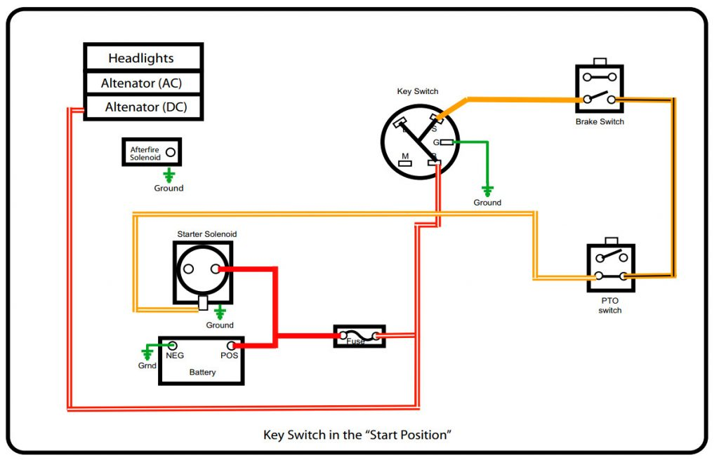
The diagrams for ignition wiring depict the wires used to power the vehicle’s electrical supply. In general, there are four different colors-coded terminals that are used for each component. The red color is used for accessories and yellow is for the battery, while green is for the starter solenoid. The “IGN terminal” is used to power the wipers along with other operational features. The diagram illustrates the connection between the ACCas well as ST terminals.
The terminal BAT holds the battery. The electrical system won’t start when the battery isn’t connected. Furthermore, the switch won’t begin to turn on. If you’re not sure the location of your car’s battery located, you can review your wiring diagram to figure out where it is. The accessory terminals in your vehicle connect to the battery as well as the ignition switch. The BAT connector is connected to your battery.
Some ignition switches include an accessory position where users can adjust their outputs and manage them without the need to use the ignition. Customers sometimes want an auxiliary output that can be used separately from the ignition. To allow the auxiliary output to be used, wire the connector with the same shade as the ignition. Then , connect it to the ACC end of the switch. While this is a convenient option, there’s an significant difference. Most ignition switches will be in an ACC position when the vehicle is in the ACC however, they will be at the START position when the car is in IGN.
Gallery of Murray Lawn Mower Ignition Switch Wiring Diagram
Gallery of Murray Lawn Mower Ignition Switch Wiring Diagram


