Crane Ignition Hi 6rc Wiring Diagram – We will first examine the various types of terminals that are found in the ignition switch. These include terminals for Coil, Ignition Switch, and Accessory. Once we’ve determined the function of the terminals we can determine the various components of the ignition wiring. We will also discuss the functions of the Ignition switch and Coil. We will then turn our attention towards the accessories terminals.
Terminals for ignition switches
An ignition switch contains three different switches that direct the battery’s current to various destinations. The ON/OFF setting of the switch that controls the ignition is managed by the first switch, which supplies power to the choke when it is pushed. Different manufacturers have different colour-coding systems that correspond to the conductors. OMC utilizes this method. The ignition switch is also equipped with a connector for adding an Tachometer.
Although the majority of ignition switch terminals may not be authentic, the numbering of each one may not be in line with the diagram. Before you plug into the ignition switch ensure that you check the continuity. A multimeter is a good instrument to verify the continuity. Once you’ve verified the continuity of the wires you can then connect the connector. If your car has an ignition switch that is installed, the wiring diagram will differ.
You must first understand the ways in which the ACC outputs and auxiliary outputs function in order to join them. The ACC, IGN and START terminals are the primary connections to the ignition switch. They also function as the primary connections to your radio and stereo. The ignition switch operates the engine’s off/on button. On older cars, the ignition switch terminals are marked with the alphabets “ACC” and “ST” (for distinct magnetic wires).
Coil terminals
To determine the type of ignition coil, the initial step is to understand the terminology. An ignition wiring diagram will reveal a variety of terminals and connections, comprising two primary and two secondaries. The voltage that operates on each coil differs. This is why it is important to first test the voltage at S1 (primary terminal). S1 must also be subjected to resistance testing to determine if it is a Type A or B coil.
The low-tension side of the coil needs to be connected to the chassis’ negative. This is also the ground in an ignition wiring diagram. The high-tension side delivers positive direct to the spark plugs. For suppression purposes the coil’s metal body is required to be connected to the chassis. It is not required to use electricity. The wiring diagram for the ignition will explain how to connect the terminals of the negative or positive coils. There could be an ignition coil problem that is easily identified by scanning it at an auto parts retailer.
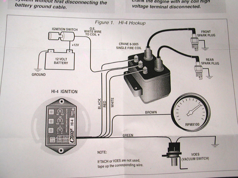
The black-and-white-striped wire from the harness goes to the negative terminal. The white wire also is black with a trace on it and it connects to the positive terminal. The black wire is connected to the contactbreaker. You can examine the connections using a paperclip to pull the wires out from the housing. It’s also essential to ensure that the terminals don’t bend.
Accessory terminals
Diagrams of ignition wiring show the different wires that are utilized to power the vehicle’s various parts. There are generally four color-coded terminus for each component. To identify accessories, red stands for starter solenoid, yellow for battery and blue for accessories. The “IGN” terminal is utilized to turn on the car, turn on the wipers, as well as other functions. The diagram illustrates how you can connect ACC or ST terminals and the rest.
The terminal BAT connects the battery to the charger. The battery is essential to allow the electrical system to begin. A dead battery can make the switch not turn on. It is possible to view the wiring diagram of your car to see the location of your car’s batteries. located. Your car’s accessory terminals connect to the ignition switch and the battery. The BAT Terminal is connected to the battery.
Some ignition switches come with a separate “accessory” position, where users can control their outputs with no ignition. Some customers may prefer to use the auxiliary output in addition to the ignition. In order for the auxiliary output be used, connect the connector in the same color as the ignition. Then connect it with the ACC end of the switch. This is an excellent feature, however there’s an important distinction. Most ignition switches come with an ACC position when your car is in the ACC mode and a START mode when it is in IGN.
Gallery of Crane Ignition Hi 6rc Wiring Diagram
Gallery of Crane Ignition Hi 6rc Wiring Diagram


