Wiring Diagram Toggle Switch Ignition Push Button Start – First, we will look at the various types of terminals on the ignition switch. These include the terminals for the Ignition switch, Coil, and Accessory. When we have a clear understanding of the purpose of each terminal, we can then identify the various components of the ignition wiring. In addition, we will discuss the roles of the Ignition switch and Coil. Following that, we will proceed to the Accessory Terminals.
Terminals for ignition switches
Three switches are found in an ignition switch. Each of these switches transmits the battery’s current to various places. The ON/OFF position of the switch that controls the ignition is managed by the second switch, which supplies the choke with power when it is pushed. Different manufacturers have different color-coding systems to identify different conductors. This will be covered in a separate article. OMC employs this system. This connector allows the connection of a speedometer to the ignition switch.
While many ignition switch terminals could not be original, the numbers of each one might not match the diagram. Before you plug in the ignition switch, ensure that you check the continuity. You can check this using a simple multimeter. After you’re happy with the integrity of your wires, you will be able install the new connector. If your vehicle has an installed ignition switch, the wiring diagram will differ.
To connect the ACC outputs to the auxiliary outputs of your car, you’ll need to first understand how these two connections work. The ACC and IGN connectors are the default connections of your ignition switch. The START, IGN, and ACC terminals are the primary connections to the radio or stereo, the START/IGN connections are the primary ones. The ignition switch is the engine’s switch to turn off or on. The ignition switch terminals on older vehicles are marked with the initials “ACC” and “ST” (for individual magneto wires).
Terminals for coil
The language used to decide the kind and model of an ignition coil is the most important thing. A simple diagram of the wiring will show a variety of connections and terminals, which include two primary terminals and two secondaries. The coils come with a distinct operating voltage, and the first method of determining what type you’re using is to test the voltage at S1, the primary terminal. To determine if it is an A, C, or B coil you should also test the resistance on S1’s.
The chassis’ negative must be connected to the low-tension side. It is also the ground in an ignition wiring diagram. The high-tension side supplies positive direct to the sparkplugs. For suppression purposes, the coil’s body metal is required to be connected to the chassis. It is not required for electrical use. A wiring diagram can also depict the connection between positive and negative coils. Sometimes, a damaged ignition coil can be identified with a scan at an auto parts shop.
The black-and-white-striped wire from the harness goes to the negative terminal. The negative terminal is served by the black trace joined to the white wire. The black wire connects to the contact breaker. You can remove the black wire from the plug housing using a paper clip in case you are uncertain about the connection. Make sure you ensure that the terminals have not been bent.
Accessory terminals
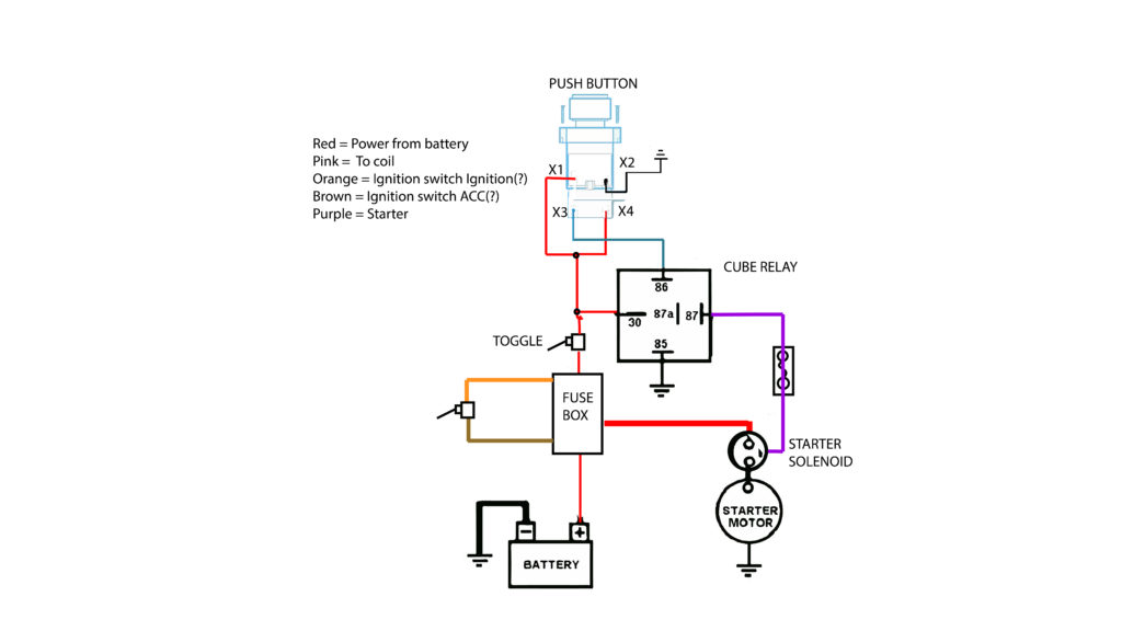
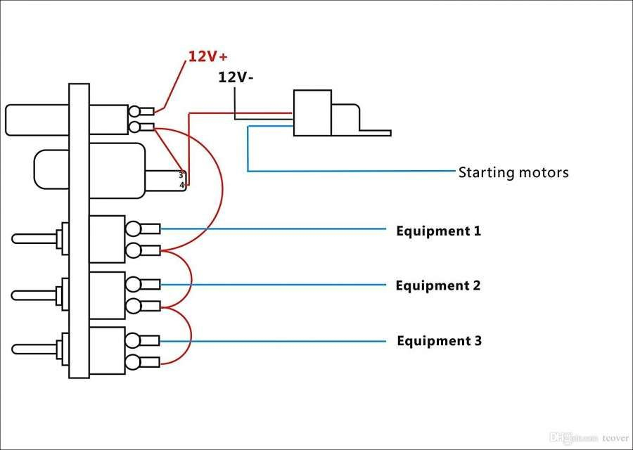
The wiring diagrams of the ignition illustrate the different wires that power the various components of the vehicle. There are generally four colored terminals that correspond to the respective component. Red is used for accessories, yellow is for the battery, and green is for the solenoid for starters. The “IGN” terminal is used to start the car, controlling the wipers and other functions. This diagram demonstrates how to connect ACC and ST terminals to the other components.
The terminal BAT is the connection to the battery. The battery is necessary for the electrical system to begin. Also, the switch won’t be able to turn on without the battery. It is possible to refer to your wiring diagram if you are not sure where the batteries of your car are. The accessory terminals on your car connect to the battery and the ignition switch. The BAT terminal connects to the battery.
Some ignition switches come with the option of an “accessory position” that allows users to modify their outputs independent of the ignition. In some cases, users may want to utilize the auxiliary output separately from the ignition. For the auxiliary output to be used, plug in the connector to the same shade as that of the ignition. Connect it to the ACC end of the switch. This is a convenient feature, but it has one major difference. Most ignition switches will be in an ACC position when the vehicle is in ACC, but they will be at the START position when the vehicle is in IGN.
Gallery of Wiring Diagram Toggle Switch Ignition Push Button Start
Gallery of Wiring Diagram Toggle Switch Ignition Push Button Start


