Key Ignition Switch Wiring Diagram – We will first look at the various types and purposes of the terminals found in the ignition switches. These terminals are for the Ignition button, Coil and Accessory. Once we have identified the purpose of these terminals then we can be able to identify the various parts of the ignition wiring. In addition, we will discuss the functions of the Ignition switch and Coil. Then, we will concentrate on the accessories terminals.
The terminals are for ignition switches.
An ignition switch is made up of three switches. They are the ones that supply the battery’s power to various locations. The first switch is the one that supplies power to the choke, while the second switch controls the ON/OFF status of the ignition switch. Different manufacturers have different color-coding systems that correspond to the conductors. OMC utilizes the same system. There is a connector in the ignition switch to allow connecting a Tachometer.
While most ignition switch terminals are duplicated, the numbers might not match the diagram. First, check the continuity of all the wires to make sure they’re properly connected to the ignition switches. A multimeter that is inexpensive can help you do this. After you have verified the integrity of the wires you are able to connect the connector. The wiring loom of an ignition switch that is supplied by the manufacturer will differ from the one you have in your car.
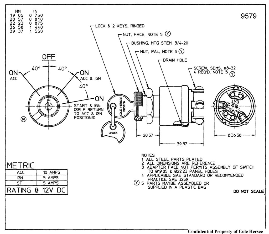
The first step is to understand the distinctions between the ACC and auxiliary outputs. The ACC and IGN connectors are the default connections of your ignition switch. The START, IGN, and ACC terminals are the primary connections for the radio or stereo, the START/IGN connections are the most important ones. The ignition switch is responsible for turning the engine of your car to and off. The terminals for the ignition switch on older vehicles are marked with the letters “ACC” as well as “ST” (for each magneto wires).
Terminals for coil
Understanding the terminology is the initial step to finding out what kind of ignition coil you own. An ignition wiring diagram will display a range of terminals and connections including two primary and two secondaries. Each coil is operating at a certain voltage. The first step to determine the kind of coil you’re using is to examine the voltage of S1 or the primary terminal. S1 should also undergo resistance tests to determine if it’s an A or B coil.
The negative of the chassis must be connected to the low-tension side. This is the ground on the diagram of ignition wiring. The high-tension supply supplies positively directly to spark plugs. The coil’s aluminum body needs to be connected to the chassis for suppression however it’s not electrically required. There are also connections of the negative and positive coil terminals on the ignition wiring diagram. In certain cases it is recommended to conduct a scan at your local auto parts store will help identify defective ignition coils.
The black-and-white-striped wire from the harness goes to the negative terminal. The white wire is black and connects to the terminal opposite. The black wire connects to the contactbreaker. If you’re unsure of the connections of the twowires, use the clip of a paperclip to remove them from the plug housing. Be sure that you don’t bend the connectors.
Accessory terminals
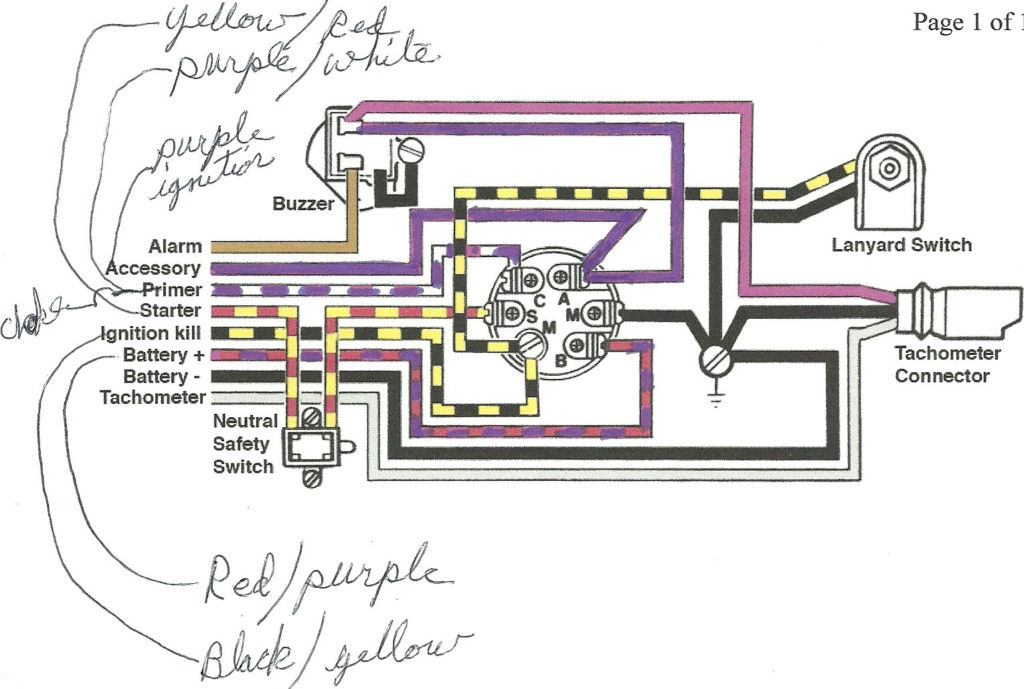
Diagrams of the ignition wiring depict the wires used to power various parts of the car. Each component has four distinct color-coded connections. Red stands for accessories, yellow represents the battery, and green for the starter solenoid. The “IGN terminal allows you to start the car, manage the wipers, or any other functions. The diagram illustrates the connection between the ACC- and ST terminals.
The terminal BAT connects the battery to the charger. The electrical system won’t start without the battery. Additionally the switch won’t come on. You may refer to the wiring diagram if you are uncertain about where the car’s batteries are located. The accessory terminals in your car connect to the ignition switch and the battery. The BAT Terminal is connected to the Battery.
Some ignition switches have the “accessory” position that allows users to regulate their outputs without needing to utilize the ignition. Sometimes, a customer wants to utilize the auxiliary output separate from the ignition. You can use the secondary output by connecting the connector to an ACC terminal on the switch that has the same color. This option is useful, but it has one key distinction. Most ignition switches come with the ACC position when your vehicle is in the ACC mode and a START mode when the switch is in IGN.
Gallery of Key Ignition Switch Wiring Diagram
Gallery of Key Ignition Switch Wiring Diagram


