Dune Buggy Ignition Switch Wiring Diagram – We will first examine the different types of terminals on the ignition switch. These are terminals that are used for Coil, Ignition Switch, and Accessory. Once we understand the function of each kind of terminal, we are able to determine the components of the ignition wiring. In addition, we will discuss the function of the Ignition switch, as well as the Coil. After that, we’ll turn our attention to Accessory terminals.
Terminals for ignition switch
There are three separate switches in the ignition switch, and they transmit the battery’s current voltage to several different locations. The first is utilized to turn on the choke through pushing it, while another switch controls the ON/OFF setting. Different manufacturers have different color-coding schemes to identify different conductors. We’ll discuss this in a separate article. OMC follows the same system. A tachometer adapter is installed on the ignition switch, allowing for the addition of a Tachometer.
While many ignition switch terminals could not be authentic, the numbering of the terminals may not be in line with the diagram. Before plugging into the ignition switch ensure that you check the continuity. A multimeter that is inexpensive can aid in this. Once you are happy with the continuity of the wires, connect the new connector. The wiring loom used in an ignition system switch that is supplied by the manufacturer is different.
It is essential to know the ways in which the ACC outputs and auxiliary outputs work in order to connect them. The ACC and IGN terminals are the default connection on the ignition switch. the START and IGN terminals are the principal connections to the radio and stereo. The ignition switch acts as the engine’s on/off button. The terminals on older cars ignition switches are marked by “ACC” and ST (for individual magneto wires).
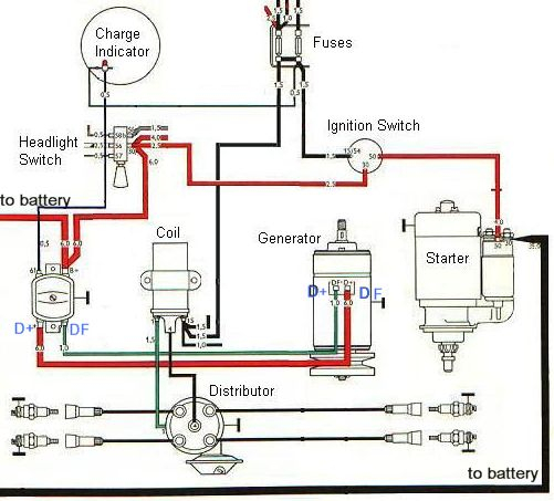
Terminals for coil
The terminology used to determine the model and type of the ignition coil is the first thing. In a typical ignition wiring diagram there are several different connections and terminals, which include two primary and two secondary. You must determine the type of coil you own by examining the voltage at the primary terminal, called S1. S1 should also be checked for resistance to determine if it’s an A, Type B, or A coil.
The chassis’ negative must be connected to the side of low-tension. This is what is known as the ground for the wiring for ignition. The high tension part supplies positive directly the spark plugs. The aluminum body of the coil needs to be linked to the chassis for suppression however it’s not electrically required. The wiring diagram for ignition will also indicate the connections of the positive coil’s terminals. Sometimes, an inspection at an auto part store can diagnose a malfunctioning ignition wire.
The black-and-white-striped wire from the harness goes to the negative terminal. The terminal that is negative is served by the black trace connected to the white wire. The black wire connects to the contact breaker. You can examine the connections with a pencil to pull the wires out of the housing. It’s also crucial to make sure the terminals don’t bend.
Accessory terminals
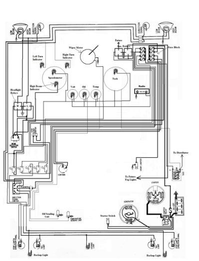
Diagrams of ignition wiring depict the wires used in the power supply of the vehicle. Each component is equipped with four distinct connections that are color coded. For accessories, red is the starter solenoid’s color, yellow for battery, and blue for accessory. The “IGN terminal” is used to run the wipers, and other operating functions. The diagram illustrates how you can connect ACC or ST terminals, and other.
The battery is connected to the terminal named BAT. The battery is necessary to allow the electrical system to get started. In addition, the switch will not begin to turn on. If you’re not sure the exact location where the battery in your car is situated, examine your wiring diagram to figure out the best way to find it. The accessory terminals of your vehicle are connected to the battery and the ignition switch. The BAT terminal connects to the battery.
Some ignition switches come with an independent “accessory” location, which allows users can control their outputs with no ignition. Sometimes, customers may wish to utilize the auxiliary input separately from the ignition. To use the additional output, wire the connector with the same colors as ignition, connecting it to the ACC terminal on the switch. This option is useful however, it does have one key distinction. Most ignition switches are set to have an ACC position when the vehicle is in the ACC position, whereas they’re set to the START position when the car is in the IGN position.
Gallery of Dune Buggy Ignition Switch Wiring Diagram
Gallery of Dune Buggy Ignition Switch Wiring Diagram


