Dyna S Single Fire Ignition Wiring Diagram – First, let’s take a look at the different types of terminals on the ignition switch. These include the terminals that are for the Ignition switch, Coil, and Accessory. After we’ve established what these kinds of terminals are used for then we can determine the various parts of the Dyna S Single Fire Ignition Wiring Diagram. In addition, we will discuss the roles of the Ignition switch, and Coil. Next, we’ll discuss the roles of the Ignition switch and Coil.
The terminals of the ignition switch
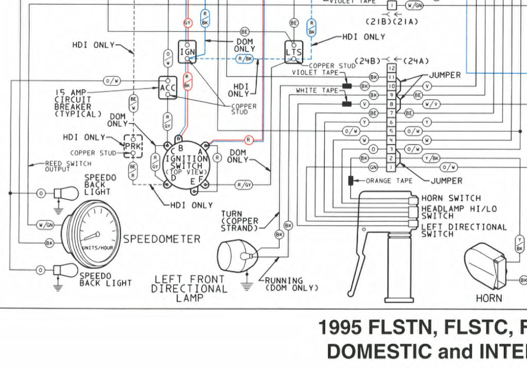
The ignition switch is comprised of three separate switches that feed the battery’s power to various destinations. The first switch powers the choke. The second switch controls the ON/OFF switch of the ignition switch. Different manufacturers have distinct colour-coding systems that correspond to the conductors. OMC follows the same system. Connectors can be connected to the ignition switch to connect the digital tachometer.
While the majority of ignition switch terminals don’t appear in their original configuration The numbering might not be in line with the diagram. To make sure that the wires are connected to the switch you must verify their continuity. A multimeter that is inexpensive can assist you in this. After you’re happy with the continuity of the wires you can install the new connector. If you have an ignition switch that is supplied by the manufacturer the wiring loom will be distinct from the one that is used in your vehicle.
It is important to understand how the ACC outputs and auxiliary outputs function in order to join them. The ACC/IGN terminals act as the default connections on the ignition switch. The START/IGN terminals connect to the stereo or radio. The ignition switch switches the car’s engine on and OFF. The terminals of older vehicles ignition switches are marked by “ACC” and ST (for individual magneto wires).
Coil terminals
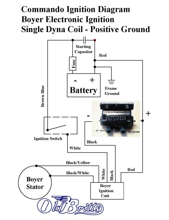
Understanding the terms is the first step to determining which type of ignition coil you have. In a simple diagram of the wiring for ignition you’ll see several different connections and terminals, such as two primary and two secondary. The operating voltage of each coil differs. It is important to first test the voltage at the S1 (primary terminal). S1 should be checked for resistance to identify if the coil is type A, B or C.
The chassis’ negative needs to be connected to the low-tension side. This is the ground of the ignition wiring. The high-tension side is a positive connection to the sparkplugs. To reduce the noise the body of the coil must be connected to the chassis. However, it is not required to connect electrically. The wiring diagram of the ignition will explain how to connect the terminals of the positive or negative coils. Sometimes, an inspection at an auto parts shop can detect a defective ignition wire.
The black-and-white-striped wire from the harness goes to the negative terminal. The negative terminal is served by the trace in black that’s joined to the white wire. The black wire connects to the contact breaker. It is possible to remove the black wire from the plug housing using a paper clip in case you are uncertain about the connection. You should also check to ensure that the terminals are not bent.
Accessory terminals
The ignition wiring diagrams show the various wires utilized for powering the various components. There are typically four different color-coded terminus for each component. The accessories are colored red while the battery is yellow, and the starter solenoid green. The “IGN” terminal can be used to start the car, control the wipers and other features. This diagram shows how to connect ACC and ST terminals with the rest of the components.
The terminal BAT is where the battery is. The electrical system can’t begin without the battery. The switch will not turn off if the battery isn’t there. To locate your car’s battery examine the wiring diagram. The accessory terminals in your car are connected to the battery as well as the ignition button. The BAT terminal is connected to the battery.
Some ignition switches come with an additional “accessory position” that lets users adjust their outputs independently of the ignition. Some customers may prefer to use the auxiliary output in addition to the ignition. The auxiliary output is used by wiring the connector in the same color as your ignition and connecting it to the ACC terminal of the switch. While this is a convenient feature, there’s one important difference. Most ignition switches are designed to show an ACC status when the vehicle is in the ACC or START positions.
Gallery of Dyna S Single Fire Ignition Wiring Diagram
Gallery of Dyna S Single Fire Ignition Wiring Diagram


