Mazda B2200 Ignition Wiring Diagram – We will first look at the various types of terminals for the ignition switch. These are the terminals that connect the Ignition, Coil, or Accessory. After we’ve identified what these terminals are then we can be able to identify the various parts of the ignition wiring. We will also discuss the roles of the Ignition switch as well as the Coil. We’ll then turn our attention to the accessory terminals.
Terminals for ignition switch
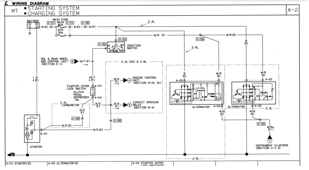
An ignition switch has three different switches that direct the battery’s power to various destinations. The ON/OFF position of the switch that controls the ignition is managed by the second switch, which supplies the choke with power when it is pushed. Different manufacturers have distinct colour-coding systems that correspond to the conductors. OMC utilizes this method. This connector allows the attachment of a speedometer to the ignition switch.
Even though some ignition switch terminals don’t appear in their original configuration however, the numbers may not match that of the diagram. You should first check the integrity of the wires to ensure that they are connected to the correct ignition switch. A cheap multimeter can aid in this. Once you’re satisfied about the continuity of your wires, you’ll be able to connect the new connector. The wiring loom used for an ignition switch that’s factory-supplied will be different than the one that you have in your car.
It is essential to know the ways in which the ACC outputs and the auxiliary outputs work in order to connect them. The ACC terminals and IGN terminals are the standard connections for the ignition switch. The START and IGN connections are the most important connections for radio and stereo. The ignition switch is responsible to turn the engine of your car on and off. Older cars have the ignition switch’s terminals that are labeled “ACC” or “ST” (for individual magnetowires).
Terminals for coil
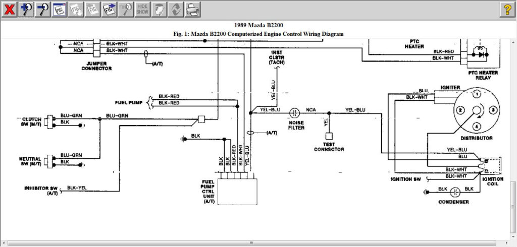
To figure out the type of ignition coil you need to know the step is to learn the terminology. A basic ignition wiring layout will show you a number of terminals and connections. Each coil comes with its own operating voltage. To determine what kind of coil you have, the first step is to test the voltage at the S1 primary terminal. S1 must also be subjected to resistance tests to determine if it are a Type A or B coil.
The chassis’ negative must be connected to the side of low-tension. This is the ground in the diagram of the ignition wiring. The high-tension part supplies the spark plugs with positive. The metal body of the coil needs to be connected to the chassis to suppress the effect however it isn’t electrically essential. You will also see the connections between the negative and positive coil terminals on the diagram of the ignition wiring. Sometimes, a damaged ignition coil can be detected through a scan performed at an auto repair shop.
The black-and-white-striped wire from the harness goes to the negative terminal. The positive terminal receives the white wire, which has a black trace. The black wire is connected to the contact breaker. If you’re not sure about the connection between the two, try using an old paper clip to take them from the housing of the plug. Make sure you ensure that the terminals aren’t bent.
Accessory terminals
The ignition wiring diagrams illustrate the different wires used to provide power to the various parts of the vehicle. Typically there are four colored terminals for each part. To identify accessories, red is the starter solenoid’s color, yellow is for battery, and blue is for accessories. The “IGN” terminal is used to turn on the car and operate the wipers and other operating functions. The diagram shows the connections to the ACC- and ST terminals.
The terminal called BAT is the place where the battery is. The electrical system won’t start without the battery. In addition, the switch doesn’t turn on. You can refer to your wiring diagram if you are not sure where the batteries of your car are. The accessory terminals in your car connect to the ignition switch, as well as the battery. The BAT connector is connected to your battery.
Some ignition switches include an accessory position where users can alter their outputs and control them without needing to use the ignition. Some customers might want to use the auxiliary input independently of the ignition. To make use of the auxiliary output, connect the connector using the same colors as ignition, connecting it to the ACC terminal on the switch. While this is an excellent feature, there’s one thing to be aware of. Most ignition switches are set to have an ACC position when the vehicle is in the ACC position, whereas they’re in the START position when the car is in the IGN position.
Gallery of Mazda B2200 Ignition Wiring Diagram

Gallery of Mazda B2200 Ignition Wiring Diagram


