Dynatek Ignition Wiring Diagram – Let’s begin by looking at different kinds of terminals that are found on the ignition switch. These include the terminals for the Ignition switch, Coil, and Accessory. Once we know the terminals that are utilized, we can begin to recognize the various parts of the Dynatek Ignition Wiring Diagram. We’ll also be discussing the functions of the Ignition switch, as well as the Coil. Then, we’ll focus on the accessory terminals.
Ignition switch terminals
The ignition switch consists of three switches. These are responsible for feeding the battery’s energy to various places. The first switch provides the choke with power when pushed, and the second is the switch that controls the ignition’s ON/OFF positions. Different manufacturers have different colors for various conductors. This is discussed in another article. OMC uses this method. An additional connector is included inside the ignition switch to allow attaching the to a tachometer.
While the majority of ignition switch terminals don’t carry an initial number, they could have a different number. To make sure that the wires are connected to the switch you should check their continuity. This can be done with a multimeter that is inexpensive. When you’re satisfied with the continuity of your wires, you will be able install the new connector. If your car has an original ignition switch supplied by the factory (or an electrical loom) the wiring loom may differ from that in your car.
Knowing how the ACC outputs are connected to the other outputs in your car is vital. The ACC and IGN terminals are the default connection on your ignition switch. the START and IGN terminals are the principal connections for stereo and radio. The ignition switch is responsible to turn the car’s engines on and off. In older vehicles, the ignition switch terminals are marked with the initials “ACC” and “ST” (for individual magnet wires).
Coil terminals
The language used to decide the model and type of an ignition coil is the first thing. You’ll see a number of connections and terminals in an ignition wiring schematic that include two primary as well as two secondary. The coils have a specific operating voltage, and the first method of determining what type you’re using is to test the voltage on S1, the main terminal. S1 should be checked for resistance to determine if the coil belongs to type A, B or C.
The low-tension end of the coil needs to be connected to the chassis the negative. This is the base of the ignition wiring. The high-tension side supplies the spark plugs with positive. To prevent noise, the coil’s metal body is required to be connected to the chassis. But, it’s not required to connect electrically. A wiring diagram can also depict the connection between positive and negative coil terminals. Sometimes, a defective ignition coil can be identified by a scan done at an auto repair shop.
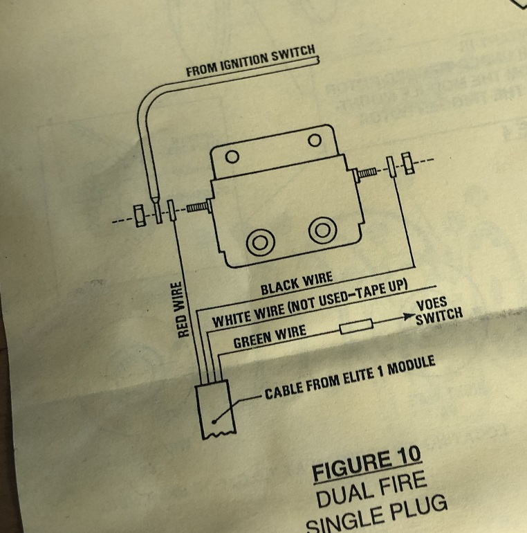
The black-and-white-striped wire from the harness goes to the negative terminal. The negative terminal is served by the black trace joined to the white wire. The black wire connects to the contactbreaker. You can take the black wire from the housing of the plug with a paper clip If you’re unsure of the connections. Be sure that the terminals aren’t bent.
Accessory terminals
Diagrams of ignition wiring illustrate the wiring used to provide power to various components of the vehicle. In general there are four distinct color-coded terminals for each component. Red refers to accessories, yellow is the battery, and green for the starter solenoid. The “IGN terminal” is used to provide power to the wipers as well as other operating features. This diagram shows how you can connect ACC and ST terminals to the other components.
The terminal BAT is the connection to the battery. The electrical system is not able to begin without the battery. The switch will not turn off if the battery isn’t there. To find the battery in your car, check your wiring diagram. The ignition switch is connected to the car’s battery. The BAT connector connects to your battery.
Some ignition switches have the “accessory” setting that permits users to control their outputs without needing to turn on the ignition. Customers may want to utilize the auxiliary output separately from the ignition. The auxiliary output can be utilized to connect the connector with the same colors as the ignition and connecting it to the ACC terminal of the switch. This convenience feature is great, but there is one differentiator. A lot of ignition switches can be set to have an ACC location when the car is in the ACC position. They will also be in the START mode when the vehicle has moved into the IGN position.
Gallery of Dynatek Ignition Wiring Diagram
Gallery of Dynatek Ignition Wiring Diagram


