Mercedes Ignition Switch Wiring Diagram – Let’s begin by examining the different types and purposes of the terminals that are found on the ignition switches. They are the terminals used that are used for Coil, Ignition Switch, and Accessory. After we’ve established what these kinds of terminals are used for, we will proceed to determine the various parts of the Mercedes Ignition Switch Wiring Diagram. Then, we will discuss the functions and the Coil. The next step is to focus to the accessory terminals.
Terminals of ignition switch
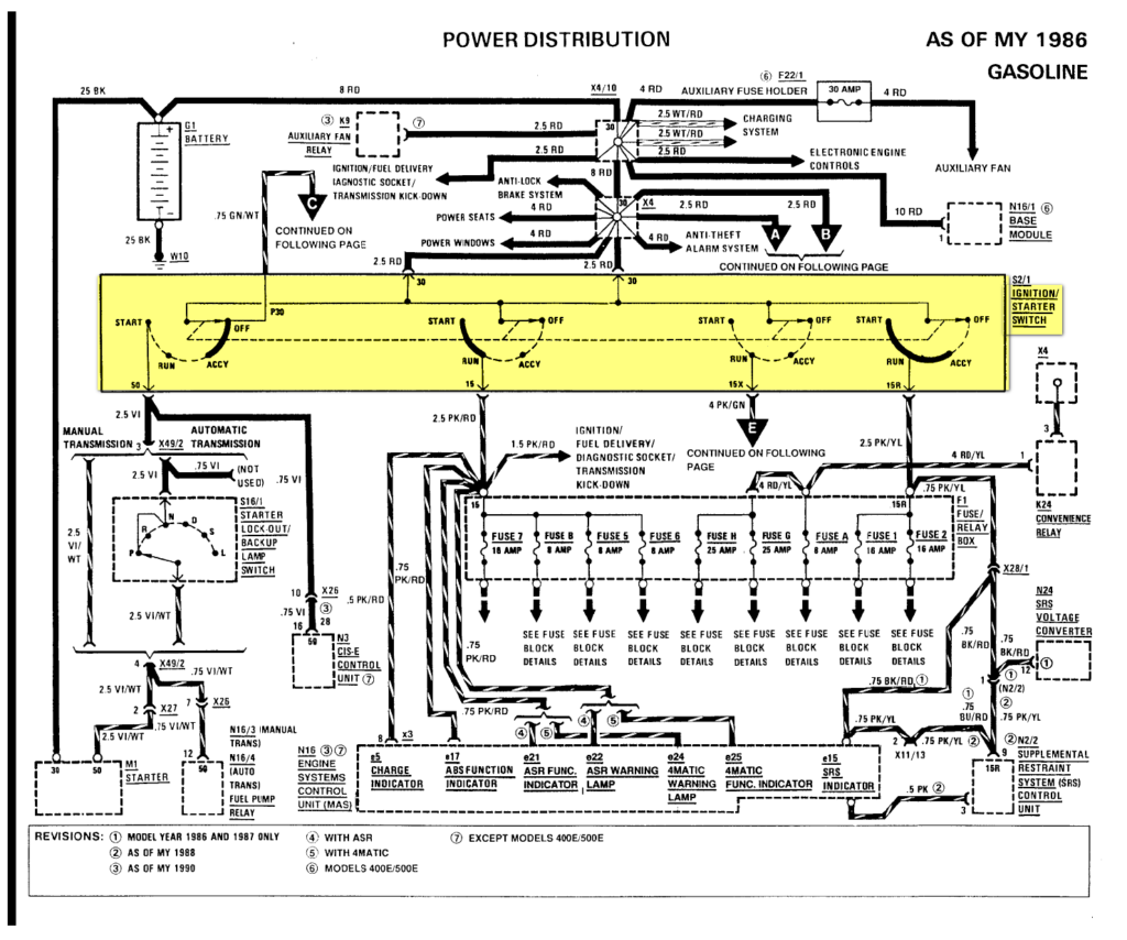
Three switches are found on an ignition switch. Each of the three switches is able to feed the battery’s voltage to several different destinations. The first switch is used to drive the choke by pushing it, while the second is for the ON/OFF setting. Different manufacturers utilize their own color-coding method for the various conductors, which is explained in a different article. OMC follows this system. This connector allows the connection of a speedometer to the ignition switch.
Although the majority of ignition switch terminals are duplicated, the numbers may not match the diagram. Check the continuity of each wire to make sure they’re properly plugged into the ignition switches. A multimeter is an excellent tool to check the continuity. After you’re happy with the continuity of your wires, you’ll be able to connect the new connector. The wiring loom of an ignition switch that is factory-supplied will be different than the one that you have in your car.
For connecting the ACC outputs to the auxiliary outputs on your car, you need to understand the way these two connections function. The ACC and IGN connectors are the default connections for the ignition switch. While the START, IGN, and ACC terminals are the main connections to the radio or stereo, the START/IGN connections are the most important ones. The ignition switch turns the car’s engine ON and OFF. On older vehicles the ignition switch’s terminals are marked with the initials “ACC” as well as “ST” (for the individual magnetic wires).
Terminals for coil
To identify the kind of ignition coil you need to know the step is to know the definition of. An ignition wiring diagram will show a variety of terminals and connections including two primary and two secondary. The operating voltage of each coil is different. This is why it is important to first test the voltage at the S1 (primary terminal). It is also recommended to test S1 for resistance in order to identify if it’s a Type A, B, or C coil.
The low-tension side of the coil needs to be connected to the chassis’ negative. It is also the ground on the diagram of ignition wiring. The high-tension component supplies the positive power directly to the spark plugs. The body of the coil has to be connected to the chassis for suppression purposes however it isn’t electrically essential. You will also see the connections between the positive and negative coil terminals on the diagram of the ignition wiring. Sometimes, a defective ignition coil is identified by a scan done at an auto repair shop.
The black-and-white-striped wire from the harness goes to the negative terminal. The white wire also has a black trace on it and it goes to the positive terminal. The black wire is connected to the contact breaker. You can remove the black wire from the housing of the plug with a paper clip if you are unsure about the connection. Make sure that the connectors aren’t bent.
Accessory terminals
Diagrams of ignition wiring show the wires that supply power to different parts of the vehicle. Each part has four distinct colored connections. The red symbol represents accessories, yellow represents the battery, and green for the starter solenoid. The “IGN terminal is used for starting the vehicle, controlling the wipers and other functions. The diagram shows how you can connect the ACC and ST terminals to the other components.
The terminal BAT connects the battery to the charger. Without the battery, the electrical system does not start. Additionally the switch won’t come on. To find your car’s battery look over your wiring diagram. The ignition switch and battery are connected via accessory terminals. The BAT terminal is connected with the battery.
Certain ignition switches provide an additional “accessory position” which allows users to modify their outputs independent of the ignition. Some customers prefer to make use of an additional output independent of the ignition. You can utilize the secondary input by connecting it to the ACC terminal. While this is an excellent feature, there’s something you need to know. Many ignition switches have an ACC position when your vehicle is in ACC mode, and a START position when the switch is in IGN.
Gallery of Mercedes Ignition Switch Wiring Diagram
Gallery of Mercedes Ignition Switch Wiring Diagram


