Fenwal Ignition Module Wiring Diagram – We’ll begin by looking at different types of terminals on an ignition switch. The terminals are the Ignition switch and Coil and the Accessory. Once we know the purpose of each kind of terminal, we are able to determine the components of the ignition wiring. We’ll also discuss the roles of the Ignition switch and Coil. Then, we’ll turn our attention to Accessory terminals.
Terminals for ignition switches
The ignition switch is comprised of three separate switches that feed the battery’s power to various locations. The first switch powers the choke. The second switch controls the ON/OFF switch of the ignition switch. Different manufacturers utilize their own color-coding method for the different conductors, that is described in a separate article. OMC utilizes this method. An additional connector is included inside the ignition switch to allow attaching a tachometer.
Although the majority of ignition switch terminals do not have an initial number, they could be equipped with a different number. The first step is to check the continuity of all the wires to ensure that they are properly plugged into the ignition switches. A simple multimeter will assist you in this. When you are satisfied with the integrity of the wires, install the new connector. If your car is equipped with an original ignition switch supplied by the factory (or an electrical loom) the wiring loom may differ from that of your car.
Understanding how the ACC outputs are connected to the other outputs in your vehicle is crucial. The ACC and IGN connectors are the standard connections for the ignition switch. Although the START, IGN, and ACC terminals are primary connections for radios or stereo, the START/IGN terminals are the primary ones. The ignition switch is the one that controls the engine of your car. The terminals on older cars ignition switches are marked by “ACC” as well as ST (for individual magneto wires).
Coil terminals
The first step in determining the type of ignition coil is to know the terminology used. A basic diagram of the wiring will reveal a variety of connections and terminals. The coils have a specific operating voltage. The first method of determining what type you’ve got is to check the voltage of S1 the main terminal. S1 must also go through resistance testing to determine whether it’s an A or B coil.
The negative end of the chassis should be connected to the coil’s low-tension side. This is what you see on the diagram of wiring. The high-tension side provides positive direct to the sparkplugs. The body of the coil has to connect to the chassis for suppression purposes, but it is not electrically necessary. The wiring diagram will also depict the connection between positive and negative coils. Sometimes, a defective ignition coil is identified with a scan at an auto parts shop.
The black-and-white-striped wire from the harness goes to the negative terminal. The negative terminal is served by the black trace connected to the white wire. The black wire connects to the contactbreaker. If you’re not sure about the connections of the two, try using a paper clip to remove them from the housing of the plug. Check that you don’t bend the connectors.
Accessory terminals
The diagrams for ignition wiring show the wires used in the vehicle’s power supply. Typically, there are four different color-coded terminals for each component. Red is for accessories, yellow is for the battery, and green is the starter solenoid. The “IGN terminal is used for starting the vehicle, controlling the wipers and other functions. The following diagram shows how to connect the ACC terminal as well as the ST terminals to the other components.
The terminal BAT is where the battery is. The electrical system is not able to start without the battery. A dead battery can cause the switch to stop turning on. You may refer to the wiring diagram if you are uncertain about where the car’s batteries are located. The accessory terminals in your vehicle are connected to the battery and the ignition button. The BAT terminal is connected to the battery.
Some ignition switches come with an additional “accessory” position, where users can control their outputs without the ignition. Sometimes, customers want to make use of an additional output independent of the ignition. In order to use the additional output, wire the connector in the same colors as ignition, connecting it to the ACC terminal on the switch. This is a great feature, however there’s one important difference. Many ignition switches have the ACC position when your car is in ACC mode and a START position when it is in IGN.
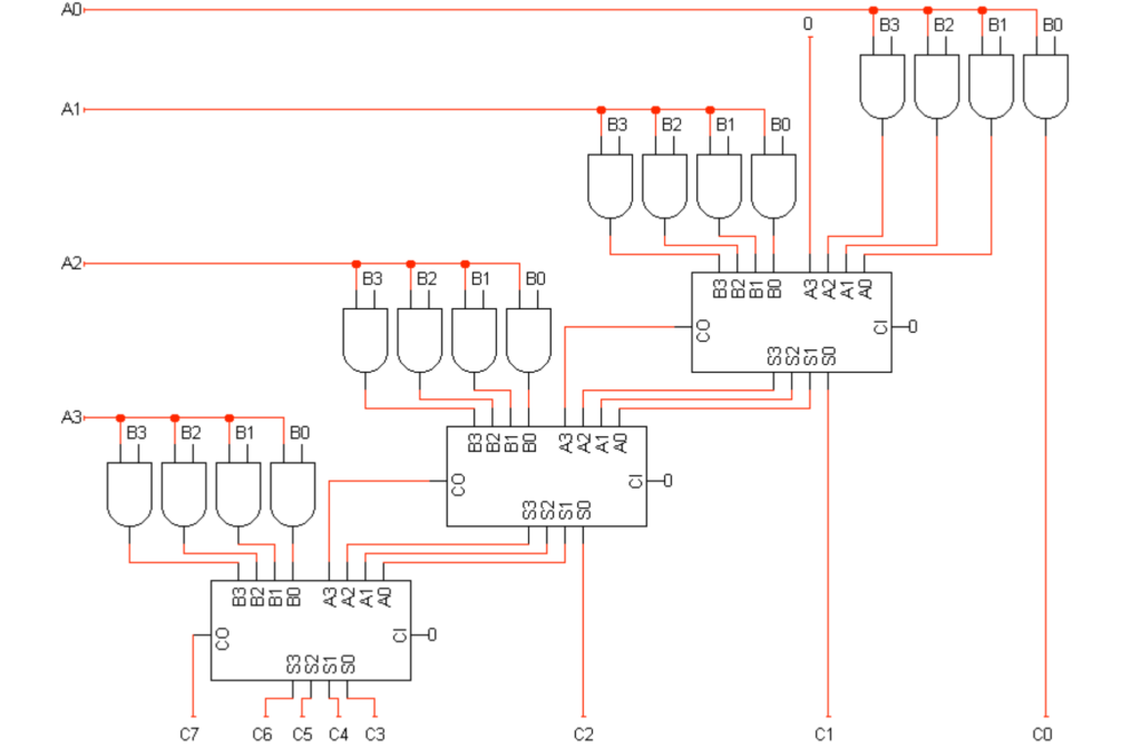
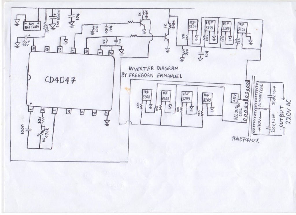
Gallery of Fenwal Ignition Module Wiring Diagram
Gallery of Fenwal Ignition Module Wiring Diagram


