Holley Sniper Efi Ignition Coil Driver Wiring Diagram – Let’s begin by looking at the different types terminals found on an ignition switch. These terminals comprise the Ignition switch and Coil as well as the Accessory. Once we know what these terminals are and what they do, we can then identify the different parts in the ignition wiring. We will also discuss the functions for the Ignition switch as well as the Coil. We will then discuss the roles of the Ignition switch as well as Coil.
Terminals for the ignition switch
An ignition switch has three separate switches that feed the battery’s current to different destinations. The choke is powered by the first switch. The second switch is responsible for the ON/OFF switch of the ignition switch. Different manufacturers have various color codes for the various conductors. This is explained in a separate article. OMC utilizes this method. A connector can be added to the ignition switch in order to connect a digital Tachometer.
While the majority of ignition switch terminals don’t come in original form The numbering might not match the diagram. Before plugging in the ignition switch, ensure that you check the continuity. A multimeter is a great tool to test the continuity. Once you are happy with the continuity of the wires it is time to install the new connector. The wiring loom used for an ignition switch that is supplied by the factory will be different from the one in your car.
Before connecting the ACC outputs to the auxiliary outputs of your car, it is important to know the fundamentals of these connections. The ACC/IGN connections function as the default connections for the ignition switch. The START/IGN connections connect to the stereo or radio. The ignition switch is accountable for turning the car’s engine on and off. Older vehicles have ignition switch’s terminals that are labeled “ACC” or “ST” (for individual magnetowires).
Terminals for coil
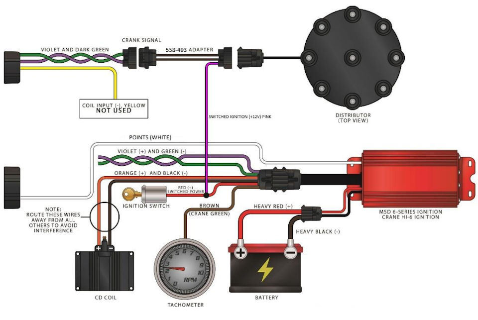
The terms used to define the model and type of an ignition coil is the first thing. A basic ignition wiring diagram will display a range of terminals and connections, comprising two primary and two secondaries. The operating voltage of each coil differs. Therefore, it is essential to first check the voltage at S1 (primary terminal). S1 should also be checked for resistance in order to identify if the coil is an A, Type B, or A coil.
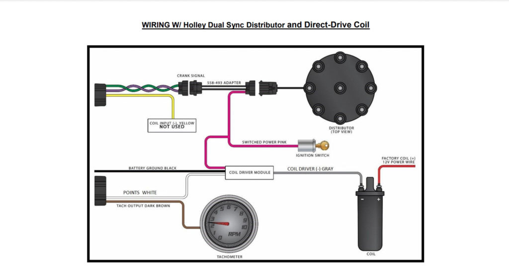
The lower-tension side of the coil must be connected to the chassis”negative. This is what you find in the wiring diagram. The high-tension side connects the spark plugs to a positive. It is required for the purpose of suppression that the coil’s metallic body be connected to the chassis, however, it is not necessary. The wiring diagram of the ignition will demonstrate how to connect the terminals of either the positive and negative coils. There could be an issue with the ignition coil that can be easily diagnosed by looking it up at an auto parts store.
The black-and-white-striped wire from the harness goes to the negative terminal. The other white wire has a black trace, and it goes to the positive terminal. The black wire connects to the contact breaker. To check the connections, use a paperclip or a pencil to pull them out of the housing for the plug. Be sure the terminals aren’t bent.
Accessory Terminals
Diagrams of ignition wiring show the various wires utilized to power the vehicle’s various parts. There are usually four different colors of terminals connected to each part. Red refers to accessories, yellow is the battery, and green is the starter solenoid. The “IGN” terminal is used to turn on the car, turn on the wipers, as well as other features. The following diagram illustrates how to connect the ACC terminal as well as the ST terminals to other components.
The terminal BAT connects the battery to the charger. The electrical system can’t begin without the battery. Additionally, the switch won’t begin to turn on. A wiring diagram can show the location of your car’s battery. The accessory terminals on your vehicle are connected to the battery and the ignition switch. The BAT connector is connected to your battery.
Certain ignition switches have an accessory position where users can alter their outputs as well as control them without needing to use the ignition. Sometimes, users want to utilize an additional output that is independent of the ignition. In order to use the auxiliary output, connect the connector with the same colors as the ignition, connecting it to the ACC terminal on the switch. This is an excellent feature, however there’s one important distinction. The majority of ignition switches are set to operate in the ACC position when the vehicle is in the ACC position, whereas they’re in the START position when the car is in the IGN position.
Gallery of Holley Sniper Efi Ignition Coil Driver Wiring Diagram

Gallery of Holley Sniper Efi Ignition Coil Driver Wiring Diagram


