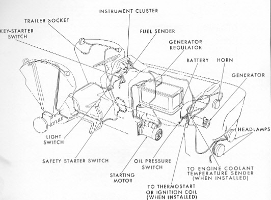
Ford 3000 Tractor Ignition Switch Wiring Diagram – First, we will take a look at the different kinds of terminals for the ignition switch. These terminals are used for the Ignition button, Coil and Accessory. Once we know what these terminals are, we will determine the various components in the ignition wiring. We will also discuss what functions are available for the Ignition switch and the Coil. After that, we will turn our attention towards the accessory terminals.
Terminals for ignition switches
Three switches are located on an ignition switch. Each of these switches transmits the battery’s current to a variety of destinations. The first switch supplies the choke with power when it is pushed. The third is the position of the ignition switch’s ON/OFF. Different manufacturers have their own color-coding system for different conductors which is documented in another article. OMC uses this method. Connectors can be attached to the ignition switch in order to connect the digital Tachometer.
Although many ignition switch terminals do not appear in their original configuration, the numbering may not match that of the diagram. The first step is to check the continuity of each wire to ensure that they are properly connected to the ignition switches. This can be accomplished using a cheap multimeter. After you’ve confirmed that the wires are in good condition, you can connect the connector. The wiring loom used for an ignition switch that is factory-supplied will be different than the one in your car.
Understanding how the ACC outputs are connected to the other outputs of your car is vital. The ACC terminals as well as the IGN terminals are the primary connections to the ignition switch. The START and IGN connections are the main connections for radio and stereo. The ignition switch regulates the engine in your car. On older vehicles the terminals of the ignition switch are marked with the alphabets “ACC” and “ST” (for individual magnet wires).
Coil terminals
The first step to determine the kind of ignition coil is to comprehend the terminology used. The fundamental diagram of ignition wiring depicts various connections and terminals. There are two primary and one secondary. It is essential to identify the type of coil you have by testing the voltage at the primary terminal, S1. It is also recommended to examine S1 for resistance to determine if it’s an A or B coil.
The low-tension end of the coil needs to be connected to the chassis’ negative. This is also the ground on the wiring diagram for ignition. The high-tension side supplies positive direct to the sparkplugs. It is essential for the purpose of suppression that the metallic body of the coil is connected to the chassis, however it isn’t essential. The wiring diagram will also illustrate the connection between the positive and negative coils. In certain instances it is recommended to conduct a scan at your local auto parts store can help you identify malfunctioning ignition coils.
The black-and-white-striped wire from the harness goes to the negative terminal. The terminal that is negative is served by the black trace attached to the white wire. The black wire is connected to the contactbreaker. If you’re unsure of the connections of both, you can use an old paper clip to take them from the plug housing. It is also important to make sure that the connections aren’t bent.
Accessory terminals
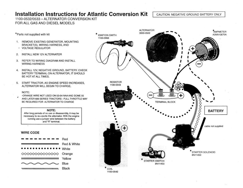
Diagrams of the ignition wiring show the wires that provide power to various components of the vehicle. There are typically four different colors-coded terminus of each part. Red stands for accessories, yellow is for the battery and green for the solenoid for starters. The “IGN” terminal is used to start the car , and also to operate the wipers, as well as other operating features. The diagram below shows how to connect the ACC terminal and ST terminals to the other components.
The terminal known as BAT is the place where the battery is. The electrical system can’t be started without the battery. Additionally, the switch won’t begin to turn on. The wiring diagram will show you the location of the battery in your car. The ignition switch and the battery are connected through the accessory terminals. The BAT terminal connects to the battery.
Some ignition switches include an accessory position where users can adjust their outputs as well as control them without the need to use the ignition. Sometimes, customers may wish to utilize the auxiliary output separately from the ignition. You can use the auxiliary output by connecting the connector to the ACC terminal on the switch that has the same color. While this is a convenient option, there’s an significant difference. Most ignition switches will have an ACC position if the car is in the ACC however, they will be at the START position if the car is in IGN.
Gallery of Ford 3000 Tractor Ignition Switch Wiring Diagram
Gallery of Ford 3000 Tractor Ignition Switch Wiring Diagram


