Ford Diesel Tractor Ignition Switch Wiring Diagram – The first step is to examine the different types of terminals on the ignition switch. These include the terminals for the Ignition switch, Coil, and Accessory. Once we know the purpose of each kind of terminal, we are able to determine the components of the ignition wiring. We’ll also be discussing the function of the Ignition switch and Coil. We’ll then turn our attention to the accessory terminals.
Terminals for ignition switch
An ignition switch is made up of three switches. These are the ones that supply the battery’s power to various places. The choke is powered by the first switch. The second switch is responsible for the ON/OFF of the ignition switch. Different manufacturers have different color-coding schemes to identify different conductors. This will be covered in another article. OMC follows the same system. The ignition switch comes with an adapter for the addition of a tachometer.
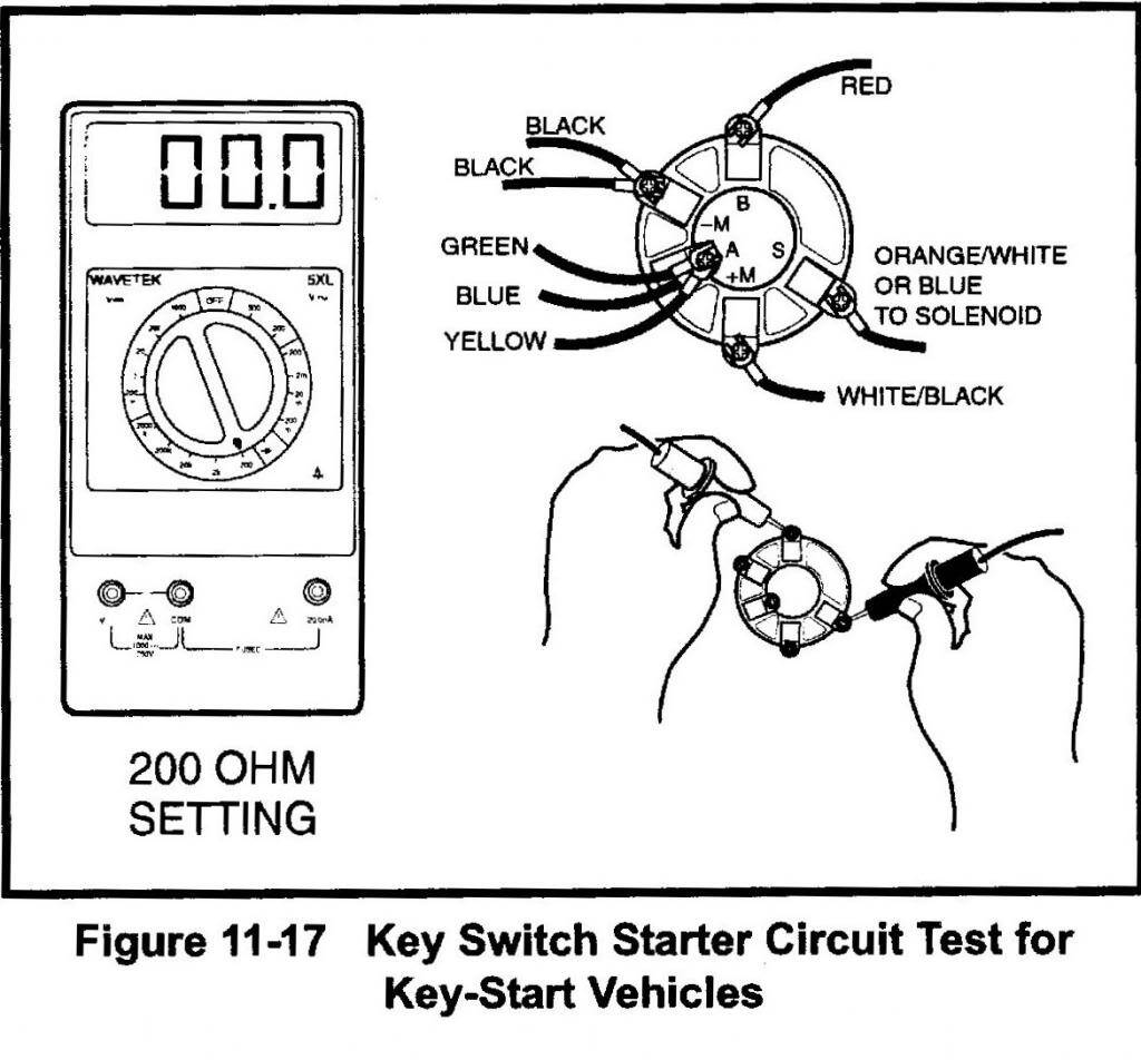
While most ignition switch terminals are not original, the numbering for each may not match the diagram. Verify the electrical continuity first to ensure they’re connected correctly to the ignition switch. This can be accomplished using a cheap multimeter. When you’re satisfied that the wires are in good order then you can connect the new connector. The wiring loom used for an ignition switch that’s supplied by the manufacturer will differ from the one in your car.
Knowing how the ACC outputs connect to the auxiliary outputs of your car is essential. The ACC and IGN connectors are the default connections of your ignition switch. The START, IGN, and ACC terminals are the primary connections for radios or stereo, the START/IGN terminals are the main ones. The ignition switch switches the engine of your car ON and off. The terminals for the ignition switch on older cars are identified with the alphabets “ACC” as well as “ST” (for individual magneto wires).
Terminals for coil
The language used to decide the model and type of the ignition coil is the most important thing. A basic ignition wiring diagram will reveal a variety of terminals and connections comprising two primary and two secondaries. The coils have a specific operating voltage, and the first step in determining which type you’ve got is to check the voltage on S1, the primary terminal. S1 must be checked for resistance to identify if the coil is Type A, B, or C.
The coil’s low-tension end must be connected to the chassis positively. This is the ground on the wiring diagram for ignition. The high-tension component supplies positively direct to the spark plugs. It is essential for the purpose of suppression that the metallic body of the coil is connected to its chassis however it isn’t essential. The wiring diagram will illustrate the connection between the positive and negative coils. In certain instances scanning the local auto parts store will help identify defective ignition coils.
The black-and-white-striped wire from the harness goes to the negative terminal. The positive terminal also gets the white wire that is black in its trace. The black wire is connected to the contactbreaker. To confirm the connection, make use of a paperclip or pencil to remove them from the plug housing. Check that you don’t bend the connectors.
Accessory terminals
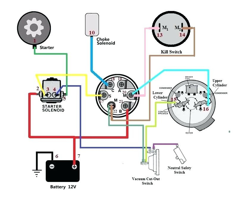
Diagrams of ignition wiring show the different wires used for powering the various components. There are generally four color-coded terminals to each component. Red is for accessories, yellow is for the battery, while green is for the solenoid for starters. The “IGN” terminal can be used to start the vehicle and control the wipers, as well as other operating features. The diagram illustrates how to connect ACC or ST terminals and the rest.
The terminal BAT connects the battery to the charger. The electrical system will not start when the battery isn’t connected. The switch also won’t be able to turn on without the battery. A wiring diagram can inform you the location of the battery in your car. The ignition switch is connected to the battery of your car. The BAT terminal is connected to the battery.
Certain ignition switches have an additional position. This lets users access their outputs from a different place without having to turn on the ignition. Customers sometimes want an auxiliary output that can be used independently from the ignition. You can use the secondary input by connecting it to the ACC terminal. Although this is a useful feature, there is one crucial distinction. A lot of ignition switches can be set to have an ACC location when the car has been moved into the ACC position. They also will be in START mode when the vehicle has moved into the IGN position.
Gallery of Ford Diesel Tractor Ignition Switch Wiring Diagram
Gallery of Ford Diesel Tractor Ignition Switch Wiring Diagram


