Harley 3 Wire Ignition Switch Wiring Diagram – The first step is to take a look at the different types of terminals used on the ignition switch. These are the terminals that connect the Ignition, Coil, or Accessory. Once we’ve determined the function of the terminals we will be able to determine the various components of the ignition wiring. We’ll also discuss the functions and the Coil. After that, we will concentrate on the accessories terminals.
The ignition switch’s terminals

An ignition switch contains three separate switches that feed the battery’s power to various destinations. The ON/OFF setting of the ignition switch is controlled by the third switch, which provides power to the choke when it’s pulled. Different manufacturers use different color-coding systems that correspond to the conductors. OMC uses the same method. A connector can be added to the ignition switch in order to connect a digital Tachometer.
Although the majority of ignition switch terminals don’t have an original number, they might have a different one. Before you plug in the ignition switch, be sure to test the continuity. A multimeter that is inexpensive can help you do this. Once you are satisfied with the continuity of the wires you can connect the new connector. The wiring loom of the ignition switch supplied by the manufacturer will differ from the one that you have in your vehicle.
The first step is to understand the distinctions between the ACC and the auxiliary outputs. The ACC and IGN terminals are the default connections for the ignition switch. the START and IGN terminals are the principal connections for the stereo and radio. The ignition switch is the one that turns the engine of your car to and off. The ignition switch terminals on older vehicles are marked with the initials “ACC” and “ST” (for each magneto wires).
Coil terminals
To identify the kind of ignition coil you need to know the step is to know the terminology. In a basic ignition wiring diagram, you will see several different connections and terminals, such as two primary and two secondary. Each coil is operating at a certain voltage. The first step to determine the kind you’re using is to examine the voltage on S1, or the primary terminal. S1 should be tested for resistance in order to identify if the coil is Type A, B, and/or C.
The negative end of the chassis should be connected to the coil’s low-tension end. It is also the ground in an ignition wiring diagram. The high-tension part is a positive connection to the sparkplugs. To reduce the noise, the coil’s metal body is required to be connected to the chassis. However, it is not required to connect electrically. The ignition wiring diagram will also outline the connection of the positive coil’s terminals. There could be an issue with your ignition coil that can be easily diagnosed by looking it up at an auto parts store.
The black-and-white-striped wire from the harness goes to the negative terminal. The positive terminal also receives the white wire that has a black trace. The contact breaker is linked to the black wire. It is possible to check the connections using a paperclip to take the wires out of the housing. You should also check to ensure that the terminals aren’t bent.
Accessory terminals
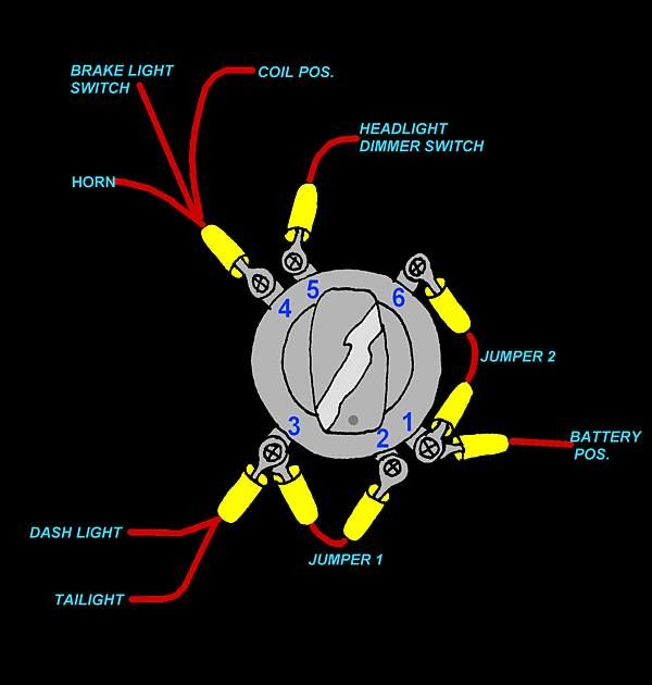
Diagrams of ignition wiring show the various wires used to power the car’s various components. There are generally four color-coded terminals to each component. The red color is for accessories, yellow the battery, and green the starter solenoid. The “IGN” terminal is used to turn on the car , and also to operate the wipers and other operating functions. This diagram shows how you can connect ACC and ST terminals with the rest of the components.
The terminal BAT is the connection for the battery. The battery is essential for the electrical system to get started. Furthermore, the switch won’t begin to turn on. The wiring diagram will inform the location of the battery of your car. The accessory terminals in your vehicle are connected to the battery and the ignition button. The BAT terminal is connected to the battery.
Certain ignition switches have an additional position. It allows users to connect their outputs to a different place without having to turn on the ignition. In some cases, users may want to use the auxiliary input separately from the ignition. The auxiliary output is utilized by wiring the connector with the same color as your ignition, and then attaching it to the ACC terminal of the switch. This is an excellent option, but there’s one important distinction. Many ignition switches can be set to have an ACC position once the car has moved into the ACC position. They will also be in START mode when the vehicle has entered the IGN position.
Gallery of Harley 3 Wire Ignition Switch Wiring Diagram
Gallery of Harley 3 Wire Ignition Switch Wiring Diagram


