Ignition Warning Light Wiring Diagram – In the beginning, we’ll take a look at the various kinds of terminals that are found on the ignition switch. These terminals are used for the Ignition button, Coil and Accessory. Once we have identified the terminals used then we can recognize the various parts of the Ignition Warning Light Wiring Diagram. In addition, we will discuss the functions of both the Ignition Switch and the Coil. Then, we’ll focus to the accessory terminals.
Terminals for the ignition switch
There are three different switches in an ignition switch, which provide the battery’s voltage to a variety of places. The first switch supplies power to the choke when it is pushed. The third is the position of the ignition switch’s ON/OFF. Different manufacturers use different color-coding methods for different conductors. We’ll discuss this in a different article. OMC utilizes this method. An adapter is included on the ignition switch to allow the addition of a tachometer.
Although some ignition switch terminals may not be original, the numbering of each may not match the diagram. To ensure that the wires are properly plugged in to the ignition switch, it is recommended to check their continuity. A multimeter that is inexpensive can help you do this. Once you’ve verified that the wires are in good condition, you can then install the connector. If you are using a factory-supplied ignition switch the wiring loom will be different from the one in your car.
Understanding how the ACC outputs are connected to the auxiliary outputs of your car is essential. The ACC and IGN connectors are the standard connections of your ignition switch. Although the START, IGN, and ACC terminals are primary connections for radios or stereo, the START/IGN terminals are the most important ones. The ignition switch regulates the engine in your car. The terminals of older cars ignition switches are identified with “ACC” and ST (for specific magneto wires).
Terminals for coil
Understanding the terms used is the initial step towards finding out the right kind of ignition coil you need. A simple diagram of the wiring will reveal a variety of terminals and connections including two primary and two secondaries. The voltage that operates on each coil differs. This is why it is important to first test the voltage at the S1 (primary terminal). S1 should also be checked for resistance to determine if it’s a Type B, B or A coil.
The chassis’ negative needs to be connected to the side of low-tension. This is the base of the ignition wiring. The high-tension supply supplies positive directly to spark plugs. To reduce the noise the body of the coil must be connected to the chassis. However, it is not required to connect electrically. The ignition wiring diagram will also show you how to connect the positive and negative coil’s terminals. There could be an issue with your ignition coil that is easily identified by scanning it at an auto parts store.
The black-and-white-striped wire from the harness goes to the negative terminal. The terminal that is negative is served by the black trace connected to the white wire. The black wire is connected to the contact breaker. To test the connections between the two wires, employ a paperclip to lift them off the housing. It’s also crucial to make sure that the terminals do not bend.
Accessory terminals
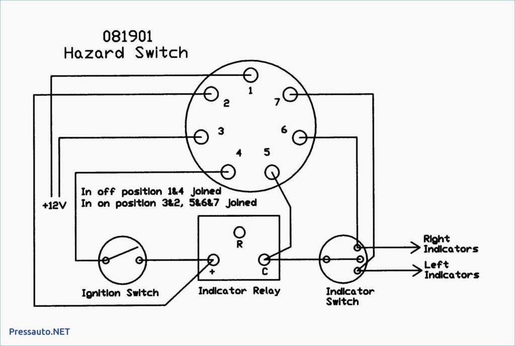
The wiring diagrams for the ignition show the various wires that are used to power various components of the vehicle. Each part has four distinct colored connections. The accessories are red while the battery is yellow, and the starter solenoid is green. The “IGN” terminal can be used to start the car, turn on the wipers and other functions. The diagram illustrates how you can connect ACC or ST terminals as well as the rest.
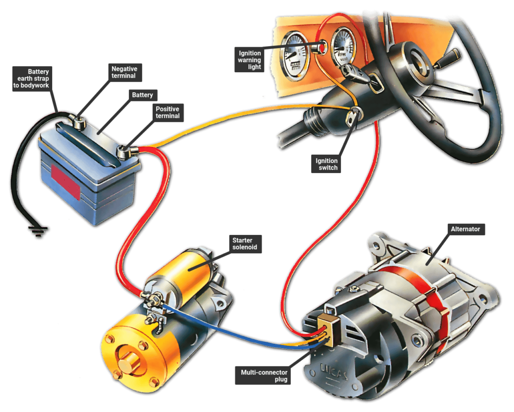
The terminal BAT connects the battery to the charger. The electrical system won’t start in the event that the battery isn’t connected. In addition, the switch will not start. To locate your car’s battery examine the wiring diagram. The accessory terminals in your car are connected to the battery and the ignition switch. The BAT terminal connects to the battery.
Some ignition switches come with an accessory position. This lets users access their outputs from a different location without having to turn on the ignition. In some cases, users may want to use the auxiliary input separately from the ignition. Use the additional output by connecting the connector to the ACC terminal on your switch that has the same color. This is a great feature, however there’s one important distinction. A lot of ignition switches can be set to have an ACC location when the car has been moved into the ACC position. They’ll also be in the START mode after the vehicle has been moved into the IGN position.
Gallery of Ignition Warning Light Wiring Diagram
Gallery of Ignition Warning Light Wiring Diagram


