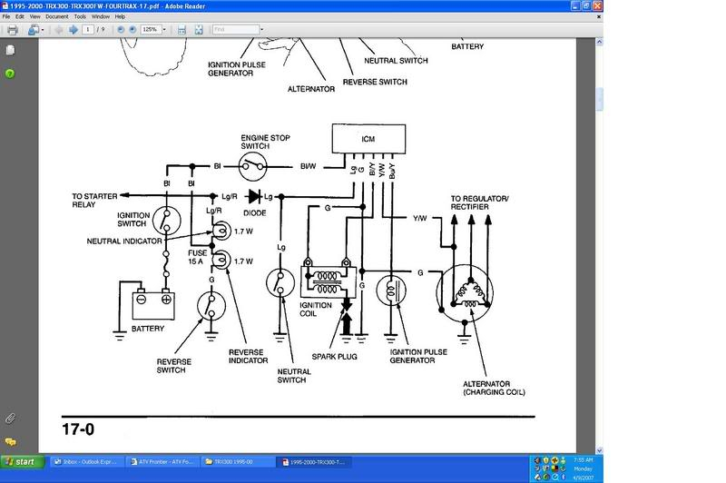
Honda 300 Fourtrax Ignition Wiring Diagram – The first step is to examine the various terminals used on the ignition switch. These terminals are for the Ignition button, Coil and Accessory. Once we know the purpose of each kind of terminal, we can then identify the various components of the ignition wiring. We’ll also discuss the functions of the Ignition switch and Coil. Next, we’ll discuss the functions of the Ignition switch as well as Coil.
The terminals of the ignition switch
An ignition switch is comprised of three switches. They supply the voltage of the battery to many different places. The first switch provides power to the choke whenever it is pushed. The second is the position of the ignition switch’s ON/OFF. Each manufacturer has its individual color-coding system that we will discuss in another article. OMC utilizes this method. A connector can be added to the ignition switch in order to add an electronic Tachometer.
Although the majority of ignition switch terminals don’t have an original number, they might have a different one. Check the electrical continuity to see if they are plugged into the ignition switch correctly. A cheap multimeter can aid in this. When you are happy with the continuity of the wires it is time to connect the new connector. If your vehicle has an original ignition switch supplied by the factory (or a wiring loom) The wiring loom may differ from that in your car.
Knowing how the ACC outputs are connected to the auxiliary outputs inside your car is vital. The ACC terminals as well as the IGN terminals serve as the primary connections to your ignition switch. The START and IGN connections are the main connections for radio and stereo. The ignition switch operates the engine’s on/off button. On older vehicles the ignition switch’s terminals are identified with the initials “ACC” and “ST” (for individual magnet wires).
Coil terminals
The terminology used to determine the kind and model of the ignition coil is the primary thing. You’ll see a number of connections and terminals on a basic ignition wiring schematic which includes two primary as well as two secondary. Each coil is equipped with a distinct operating voltage. To determine which type of coil you have, the first step is to test the voltage at the S1 primary terminal. S1 must also be subjected to resistance testing to determine if it is a Type A or B coil.
The low-tension coil side must be connected at the chassis’s less. This is the ground on the ignition wiring diagram. The high-tension side provides positive direct to the sparkplugs. The metal body of the coil needs to connect to the chassis to suppress the effect but is not electrically necessary. A wiring diagram can depict the connection between positive and negative coils. Sometimes, a visit to an auto parts store could identify a problem with the ignition wire.
The black-and-white-striped wire from the harness goes to the negative terminal. The positive terminal also receives a white wire that includes a black trace. The black wire is connected to the contact breaker. You can remove the black wire from the housing of the plug with a paper clip if you are unsure about the connections. Make sure that the terminals do not bend.
Accessory Terminals

The diagrams for ignition wiring depict the wiring used in the power supply of the vehicle. There are generally four color-coded terminals to each component. For accessories, red stands for starter solenoid, yellow is for battery and blue for accessories. The “IGN” terminal is used for starting the car, operating the wipers, and for other functions. The diagram shows how you can connect the ACC and ST terminals to the rest of the components.
The terminal BAT is the connector for the battery. Without the battery the electrical system can not start. A dead battery can cause the switch to stop turning on. A wiring diagram can show the location of your car’s battery. The accessory terminals in your vehicle are connected to the battery and ignition button. The BAT connector is connected to your battery.
Certain ignition switches have an accessory position. It allows users to connect their outputs to a different location without having to turn on the ignition. Some customers want an auxiliary output that can be used separately from the ignition. You can use the additional input by connecting the connector to the ACC terminal. Although this is a useful feature, there’s one crucial distinction. Most ignition switches come with an ACC position when the car is in ACC mode, and a START position when it is in IGN.
Gallery of Honda 300 Fourtrax Ignition Wiring Diagram
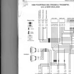
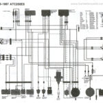
Gallery of Honda 300 Fourtrax Ignition Wiring Diagram


