Ford 302 Ignition Wiring Diagram – Let’s first examine the various terminals that are used in the ignition switch. These are terminals that are used for Coil, Ignition Switch, and Accessory. Once we have established what these types of terminals are used for, we will proceed to determine the various parts of the Ford 302 Ignition Wiring Diagram. We will also discuss the function of the Ignition switch and Coil. Then, we’ll turn our attention to the Accessory terminals.
Terminals for ignition switches
An ignition switch has three switches. They feed the battery’s voltage to many different places. The choke is powered by the first switch. The second switch controls the ON/OFF of the ignition switch. Different manufacturers have different color-coding systems that correspond to the conductors. OMC uses the same method. Connectors can be connected to the ignition switch in order to add an electronic Tachometer.
Even though the majority of ignition switch terminals don’t have the original design however, the numbers may not match the diagram. It is important to first verify the electrical continuity to see if they are plugged into the ignition switch correctly. This can be done with a multimeter that is inexpensive. When you’re satisfied that all wires are in good continuity, you can attach the new connector. If your vehicle is equipped with an installed ignition switch the wiring diagram may differ.
First, understand the differences between the ACC and auxiliary outputs. The ACC, IGN and START terminals are your default connections to the ignition switch. They also serve as the primary connections to the radio and stereo. The ignition switch’s function is to turn the car’s engines on and off. On older vehicles the ignition switch’s terminals are marked with the letters “ACC” as well as “ST” (for individual magnet wires).
Terminals for coil
Understanding the terms used is the first step in finding out the right kind of ignition coil to choose. A basic ignition wiring layout will show you a number of terminals and connections. Each coil has a specific operating voltage. To determine the type of coil you have first, you need to determine the voltage at S1, the primary terminal. S1 must also go through resistance testing to determine if it are a Type A or B coil.
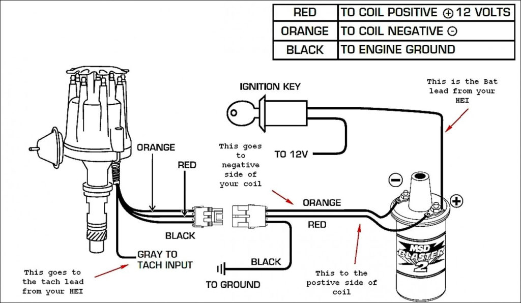
The lower-tension side of the coil must be connected to the chassis the negative. This is the base of the ignition wiring. The high tension side supplies positively directly to the spark plugs. For suppression purposes the body of the coil must be connected to the chassis. It is not necessary to electrically connect. The wiring diagram of the ignition will demonstrate how to connect the terminals of the negative or positive coils. There could be an issue with the ignition coil which can be identified by looking it up at an auto parts retailer.
The black-and-white-striped wire from the harness goes to the negative terminal. The white wire is black-colored and connects to the terminal opposite. The black wire is connected to the contact breaker. To check the connections, employ a paperclip, or a pencil to lift them out of the housing for the plug. You should also check to make sure that the connections are not bent.
Accessory terminals
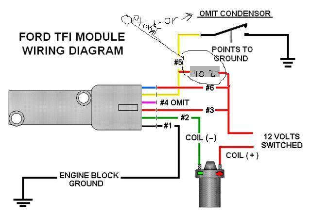
Ignition wiring diagrams show the various wires utilized to power the vehicle’s various components. There are typically four colors of terminals connected to each part. Red is used for accessories and yellow is for the battery, while green is for the starter solenoid. The “IGN” terminal is used to start the car, operating the wipers and other functions. The diagram illustrates how to connect ACC or ST terminals as well as the rest.
The terminal called BAT is where the battery is connected. The electrical system won’t start without the battery. Furthermore, the switch won’t start. You can refer to your wiring diagram if you’re not sure where the batteries of your car are. The accessory terminals in your car connect to the ignition switch, as well as the battery. The BAT terminal is connected to the battery.
Some ignition switches come with an additional “accessory position” that allows users to adjust their outputs independently of the ignition. Some customers may prefer to utilize the auxiliary output in addition to the ignition. For the auxiliary output to be used, plug in the connector in the same shade as that of the ignition. Then , connect it to the ACC end of the switch. While this is an excellent feature, there is one significant difference. Many ignition switches have an ACC position when your vehicle is in ACC mode, and a START position when you are in IGN.
Gallery of Ford 302 Ignition Wiring Diagram
Gallery of Ford 302 Ignition Wiring Diagram


