Mercury 6 Wire Ignition Switch Wiring Diagram – We will first look at the various types of terminals on the ignition switch. These terminals comprise the Ignition switch as well as the Coil along with the Accessory. Once we understand the function of each terminal, we can then determine the components of the ignition wiring. We will also discuss the roles of the Ignition switch and Coil. Then we’ll discuss the Accessory Terminals.
Terminals for the ignition switch
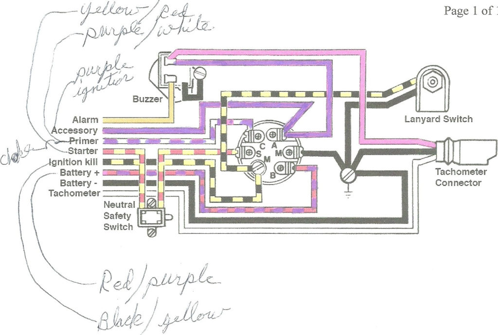
There are three different switches on the ignition switch, and they provide the battery’s voltage to various destinations. The ON/OFF setting of the ignition switch is controlled by the third switch, which delivers power to the choke whenever it’s pulled. Different manufacturers have different colors for various conductors. This is described in another article. OMC utilizes this method. The ignition switch also includes an option to connect the Tachometer.
While most ignition switch terminals are duplicated, the numbers might not be consistent with the diagram. Examine the integrity of the wires first to make sure they are correctly plugged in the ignition switch. A multimeter that is inexpensive can assist you in this. Once you’ve verified that the wires are in good condition, you can then connect the connector. If your vehicle has an ignition switch that is installed the wiring diagram will differ.
Before you can connect the ACC outputs to the auxiliary outputs of your car, it is important to know the fundamentals of these connections. The ACC, IGN and START terminals are the primary connection to the ignition switch. They also serve as the main connections to the radio and stereo. The ignition switch is the one that controls the engine of your car. The terminals of older cars’ ignition switches are labeled with “ACC” as well as ST (for individual magneto wires).
Terminals for coil
To identify the kind of ignition coil you need to know the step is to understand the terms. A basic diagram of the wiring will reveal a variety of terminals and connections. The voltage that operates on every coil is different. This is why it is important to first test the voltage at the S1 (primary terminal). S1 should also be checked for resistance to determine if the coil is an A, Type B, or an A coil.
The negative of the chassis must be connected to the low-tension side. This is what is known as the ground for the wiring for ignition. The high-tension side supplies positively directly to the spark plugs. It is essential for suppression purposes that the body of the coil’s metal be connected to the chassis, but not essential. A wiring diagram can illustrate the connection between the positive and negative coil terminals. Sometimes, a malfunctioning ignition coil can be identified through a scan performed at an auto parts shop.
The black-and-white-striped wire from the harness goes to the negative terminal. The terminal for the negative is served by the black trace that’s joined to the white wire. The black wire connects to the contact breaker. You can examine the connections using a paperclip to pull the wires out from the housing. It is also important to make sure that the terminals do not bend.
Accessory terminals
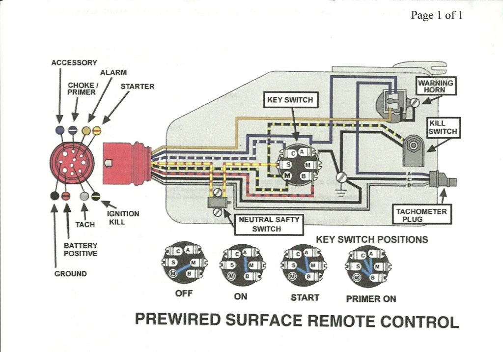
Ignition wiring diagrams depict the various wires that are used to power different components. There are typically four different color-coded terminus for each component. The red color is used for accessories while yellow is the battery, while green is the starter solenoid. The “IGN terminal is used to start the car, operating the wipers and other functions. The diagram below shows how to connect the ACC terminal as well as the ST terminals to the other components.
The terminal BAT connects the battery to the charger. The battery is essential to allow the electrical system to begin. Also, the switch won’t turn on without the battery. You can view your wiring diagram to determine where your car’s batteries are located. The accessory terminals on your vehicle connect to the battery as well as the ignition switch. The BAT Terminal is connected to the battery.
Certain ignition switches come with the “accessory” position that permits users to regulate their outputs without having to use the ignition. Sometimes, customers would like an auxiliary output that can be operated independently of the ignition. To use the additional output, wire the connector using the same colors as ignition and connect it to the ACC terminal on the switch. This is a great convenience feature however, there’s one difference. Most ignition switches come with an ACC position when your car is in the ACC mode and a START position when the switch is in IGN.
Gallery of Mercury 6 Wire Ignition Switch Wiring Diagram
Gallery of Mercury 6 Wire Ignition Switch Wiring Diagram


