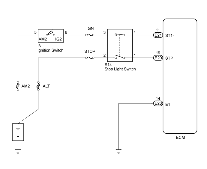
S14 Ignition Wiring Diagram – We will first look at the various kinds and functions of terminals in the ignition switches. These are terminals for the Ignition, Coil, or Accessory. Once we have identified the terminals that are utilized and which ones are not, we can recognize the various parts of the S14 Ignition Wiring Diagram. We will also discuss the functions for the Ignition switch and the Coil. After that, we’ll turn our attention to the Accessory terminals.
Ignition switch terminals
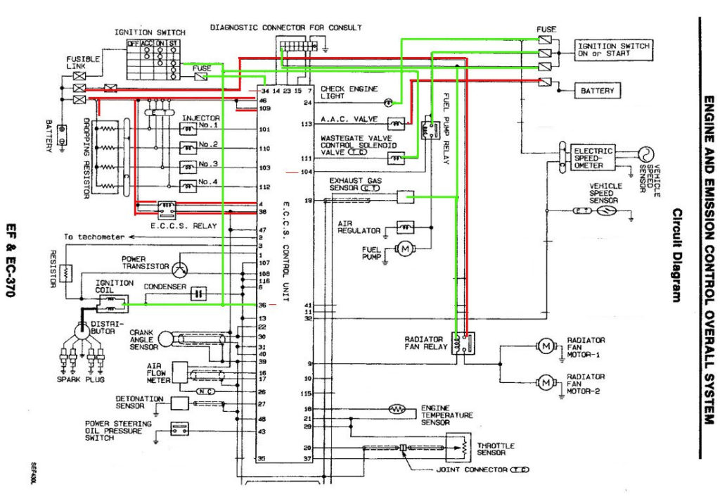
An ignition switch contains three switches that supply the battery’s power to various destinations. The ON/OFF setting of the switch that controls the ignition is managed by the second switch, which delivers power to the choke when it’s pulled. Different manufacturers have different color-coding systems for different conductors. We will cover this in another article. OMC follows the same system. This connector allows the attachment of a speedometer the ignition switch.
While most ignition switch terminals aren’t original, the numbers for each may not match the diagram. Before you plug into the ignition switch, make sure to check the continuity. A multimeter is a good tool to test the continuity. Once you’re satisfied about the integrity of the wires, then you’ll be able to connect the new connector. If your car is equipped with an original factory-supplied ignition switch (or a wiring loom) The wiring loom might differ from that of your car.
Before connecting the ACC outputs to your car’s auxiliary outputs It is essential to be familiar with the fundamentals of these connections. The ACC/IGN terminals function as the default connections for the ignition switch. The START/IGN terminals are connected to the stereo or radio. The ignition switch is the engine’s switch to turn off or on. Older cars are equipped with ignition switch’s terminals that are labeled “ACC” or “ST” (for individual magnetowires).
Terminals for coil
To identify the kind of ignition coil, the first step is to learn the terms. A basic ignition wiring layout will provide you with a range of connections and terminals. It is essential to identify the type of coil that you own by examining the voltage at the primary terminal, S1. S1 should also undergo resistance testing to determine if it is an A or B coil.
The chassis’ negative must be connected to the coil’s low-tension side. This is the wiring diagram you will see in the wiring diagram. The high-tension end supplies positive direct to the sparkplugs. For suppression purposes the coil’s body metal must be connected with the chassis. It is not required for electrical use. There are also connections between the negative and positive coil terminals on the ignition wiring diagram. You may find an issue with the ignition coil that is easily identified by scanning it at the auto parts shop.
The black-and-white-striped wire from the harness goes to the negative terminal. The other white wire is black with a trace on it, and it connects to the positive terminal. The black wire goes to the contact breaker. You can remove the black wire from the plug housing by using a paperclip If you’re unsure of the connection. It is also important to make sure that the terminals aren’t bent.
Accessory terminals
The ignition wiring diagrams show the different wires used to power various components. There are usually four color-coded terminus for each component. The red color represents accessories, yellow represents the battery and green for the starter solenoid. The “IGN” terminal allows you to start the car, manage the wipers or other operation features. This diagram shows how you can connect ACC and ST terminals with the rest of the components.
The terminal BAT holds the battery. Without the battery, the electrical system does not get started. A dead battery can cause the switch to not turn on. It is possible to look up your wiring diagram to determine where your car’s batteries are placed. The ignition switch is connected to the car’s battery. The BAT connector connects to your battery.
Some ignition switches come with an accessory position. This allows users to connect their outputs to a different place without having to turn on the ignition. Some customers might want to use the auxiliary input independently of the ignition. To make use of the additional output, wire the connector using the same colors as ignition and connect it to the ACC terminal on the switch. While this is a convenient feature, there is one important difference. Most ignition switches come with an ACC position when your vehicle is in ACC mode and a START mode when the switch is in IGN.
Gallery of S14 Ignition Wiring Diagram
Gallery of S14 Ignition Wiring Diagram


