Honda Gx630 Ignition Wiring Diagram – Let’s begin by examining the different types and functions of the terminals found on the ignition switches. These include the terminals that are for the Ignition switch, Coil, and Accessory. Once we have established what these types of terminals are, we will proceed to determine the various parts of the Honda Gx630 Ignition Wiring Diagram. In addition, we will discuss the roles of the Ignition switch and Coil. We will then focus on the accessories terminals.
The terminals of the ignition switch
Three switches can be found on an ignition switch. Each of the three switches feeds the battery’s voltage to a variety of places. The ON/OFF setting of the ignition switch is controlled by the third switch, which delivers power to the choke when it is pushed. Different manufacturers use different color-coding methods for different conductors. This will be covered in a separate article. OMC uses this method. A connector is also included inside the ignition switch to allow connecting the tachometer.
Although the majority of ignition switch terminals don’t come in original form The numbering might not match that of the diagram. Check the electrical continuity to determine if they’re connected to the ignition switch in the correct way. A multimeter that is inexpensive can assist you in this. When you’re happy with the connection then you can connect the new connector. If your vehicle has an original ignition switch supplied by the factory (or wiring loom) the wiring loom might differ from that in your car.
Before you can connect the ACC outputs to the auxiliary outputs of your car It is essential to know the fundamentals of these connections. The ACC, IGN and START terminals are the primary connections to the ignition switch. They also function as the primary connections to the radio and stereo. The ignition switch acts as the engine’s switch to turn off or on. Older cars have the ignition switch’s terminals that are labeled “ACC” or “ST” (for individual magnetowires).
Terminals for coil
To identify the kind of ignition coil you need to know the step is to learn the definition of. The fundamental diagram of ignition wiring shows a number different connections and terminals. There are two primary and secondary connections. The operating voltage of every coil is different. It is important to first test the voltage at the S1 (primary terminal). To determine if it is an A, C or B coil, you must also check the resistance of S1.
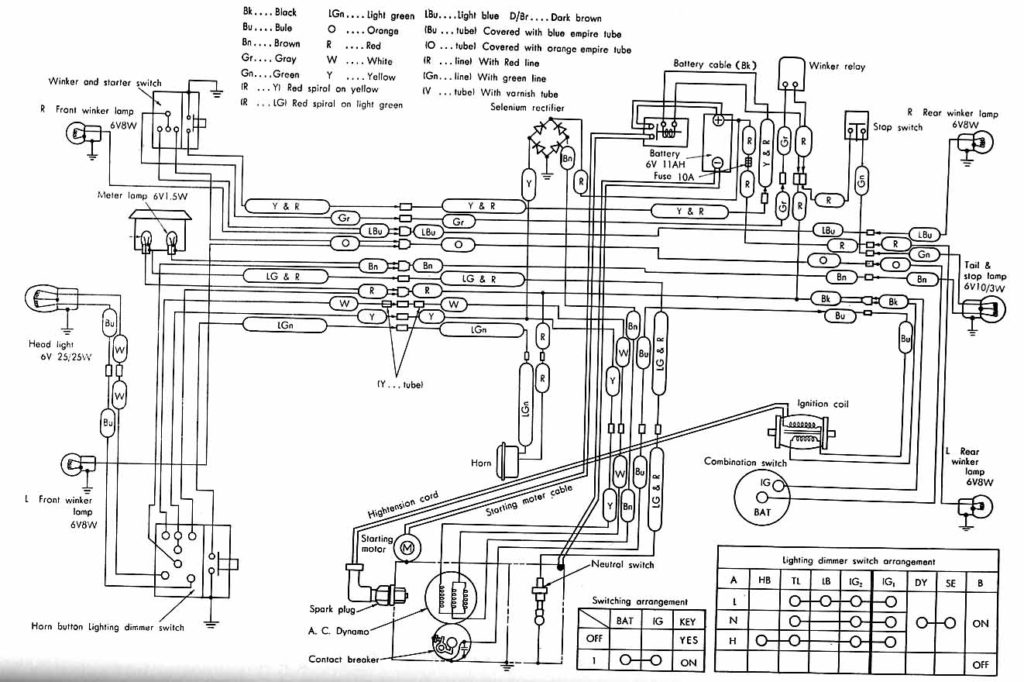
The chassis’ negative needs to be connected to the side of low-tension. This is the ground in the diagram of the ignition wiring. The high tension side provides positive power directly to the spark plugs. The aluminum body of the coil needs to be linked to the chassis for suppression however it’s not electrically required. The ignition wiring diagram will also show you the connections between the negative and positive coil’s terminals. Sometimes, a check at an auto parts store could diagnose a malfunctioning ignition wire.
The black-and-white-striped wire from the harness goes to the negative terminal. The positive terminal also receives a white wire that has a black trace. The black wire is connected to the contact breaker. To verify the wires’ connections, employ a paperclip to remove them out of the housing. Be sure the terminals do not bend.
Accessory terminals
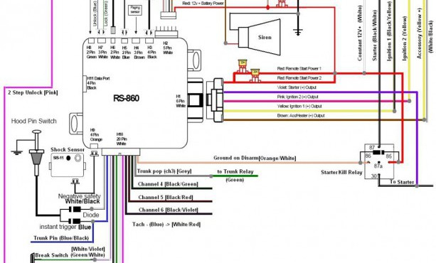
The ignition wiring diagrams illustrate the different wires that are utilized to power the vehicle’s various components. There are typically four color-coded terminals that correspond to the component. The accessories are colored red and the battery yellow the starter solenoid is green. The “IGN terminal” is used to run the wipers, along with other operational features. The diagram shows how you can connect the ACC and ST terminals to the other components.
The terminal BAT holds the battery. The electrical system won’t start without the battery. Additionally, the switch won’t begin to turn on. To find the battery in your car examine the wiring diagram. The ignition switch is linked to the car’s battery. The BAT connector is connected to your battery.
Some ignition switches come with an accessory position. This lets users access their outputs from a different location without having to turn on the ignition. Customers may want to utilize the auxiliary output independently of the ignition. The auxiliary output is used by wiring the connector with the same color as your ignition, and then attaching it to the ACC terminal of the switch. Although this is a great feature, there’s one thing to be aware of. A majority of ignition switches feature the ACC position when your car is in the ACC mode and a START position when you are in IGN.
Gallery of Honda Gx630 Ignition Wiring Diagram
Gallery of Honda Gx630 Ignition Wiring Diagram


