Outboard Motor Ignition Switch Wiring Diagram – First, we will take a look at the various kinds of terminals in the ignition switch. They include terminals for the Ignition switch, Coil, and Accessory. Once we know what these types of terminals are used for We will then determine the various parts of the Outboard Motor Ignition Switch Wiring Diagram. In addition, we will discuss the roles of the Ignition switch and Coil. Then, we’ll turn our attention to Accessory terminals.
Terminals for ignition switches
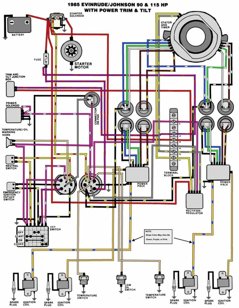
An ignition switch is made up of three switches. These are responsible for supplying the battery’s power to several destinations. The first switch is utilized to power the choke by pushing it, and the third switch is used to control the ON/OFF position. Different manufacturers have different colour-coding systems that correspond to the conductors. OMC follows the same system. The connector permits the attachment of a speedometer the ignition switch.
Although the majority of ignition switch terminals aren’t original, the numbers for each might not be consistent with the diagram. Check the continuity of all wires to make sure they’re properly plugged into the ignition switches. A multimeter is a good tool to test the continuity. After you’ve confirmed that the wires are in good condition, you can install the connector. If your car has an installed ignition switch the wiring diagram may differ.
It is important to know the differences between ACC and secondary outputs. The ACC terminals and IGN terminals are the standard connections for your ignition switch. The START and IGN connections are the primary connections for radio and stereo. The ignition switch is responsible for turning the car’s engine on and off. Older cars are identified by the initials “ACC”, “ST”, (for individual magneto cables) at the ignition switch’s terminals.
Terminals for coil
The terminology used to determine the kind and model of the ignition coil is the primary thing. In a typical diagram of the wiring for ignition, you will see various connections and terminals, such as two primary and two secondary. Each coil has an operating voltage. The first step to determine which type you have is to check the voltage at S1 or the primary terminal. Also, you should check S1 for resistance in order to determine whether it is a Type A, B, or C coil.
The low-tension coil side must be connected to the chassis’s minus. This is the ground on the ignition wiring diagram. The high-tension part connects the spark plugs to a positive. To prevent noise the body of the coil must be connected to chassis. But, it’s not required to connect electrically. The diagram of the ignition wiring will also demonstrate the connection of the positive and negative coil’s terminals. Sometimes, an inspection at an auto parts shop can diagnose a malfunctioning ignition wire.
The black-and-white-striped wire from the harness goes to the negative terminal. The positive terminal also receives the second white wire, which is black in its trace. The black wire goes to the contact breaker. You can take the black wire from the plug housing with a paper clip If you’re unsure of the connection. Make sure that the connectors aren’t bent.
Accessory terminals
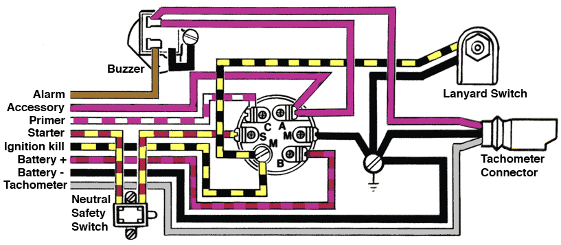
Diagrams of ignition wiring show the various wires utilized to power the vehicle’s various components. There are generally four colors-coded terminus of each part. Red stands for accessories, yellow is for the battery, and green for the solenoid for starters. The “IGN” terminal can be used to turn on the car, turn on the wipers and other features. The diagram shows how to connect ACC or ST terminals as well as the rest.
The battery is attached to the terminal called BAT. The electrical system will not start in the event that the battery isn’t connected. A dead battery could make the switch not come on. If you’re not sure the exact location where the battery in your car is situated, review your wiring diagram to figure out the best way to find it. The ignition switch as well as the battery are connected by the accessory terminals. The BAT connector is connected to the battery.
Some ignition switches come with an accessory position. This allows users to access their outputs from a different place without having to turn on the ignition. Customers may want to use the auxiliary output in addition to the ignition. You can utilize the additional input by connecting it to the ACC terminal. This option is useful, but it has one significant differentiator. A lot of ignition switches can be programmed to have an ACC position once the car has been moved into the ACC position. They’ll also be in the START position once the vehicle is moved into the IGN position.
Gallery of Outboard Motor Ignition Switch Wiring Diagram
Gallery of Outboard Motor Ignition Switch Wiring Diagram


