Massey Ferguson Tractor Ignition Switch Wiring Diagram – First, we will take a look at the different kinds of terminals on the ignition switch. These include the terminals for the Ignition switch, Coil, and Accessory. Once we know the terminals that are utilized, we can begin to identify the different components of the Massey Ferguson Tractor Ignition Switch Wiring Diagram. We will also cover the different functions of the Ignition Switch and Coil. Following that, we’ll shift our attention to the Accessory terminals.
Terminals for the ignition switch
An ignition switch has three switches that supply the battery’s current to various locations. The first one supplies the choke with power when pushed, and the second is the ignition switch’s ON/OFF position. Different manufacturers use different color-coding methods for different conductors. This will be covered in another article. OMC follows the same system. An adapter is included on the ignition switch, allowing for the addition of a tonometer.
While many ignition switch terminals may not be authentic, the numbering of each may not match the diagram. Check the continuity of each wire to ensure they are correctly connected to the ignition switches. A multimeter is a great instrument to verify the continuity. After you’re sure that all wires are running in good harmony and you are able to connect the new connector. The wiring loom in the ignition system switch supplied by the manufacturer differs.
Before connecting the ACC outputs to the auxiliary outputs of your car it is crucial to know the fundamentals of these connections. The ACC and IGN connectors are the standard connections of your ignition switch. The START, IGN, and ACC terminals are the main connections for radios or stereo, the START/IGN connections are the primary ones. The ignition switch is the one that controls the engine of your car. Older cars are equipped with ignition switch terminals labeled “ACC” or “ST” (for individual magnetowires).
Terminals for coil
Understanding the terminology is the initial step in knowing what type of ignition coil you have. You will see several connections and terminals in the basic wiring diagram for ignition that include two primary as well as two secondary. The operating voltage of each coil differs. This is why it is essential to first check the voltage at S1 (primary terminal). S1 must also be subjected to resistance tests to determine if it are an A or B coil.
The negative end of the chassis must be connected to the coil’s low-tension side. This is what’s called the ground in the wiring diagram for ignition. The high tension side supplies positive directly the spark plugs. It is essential for the purpose of suppression that the body of the coil’s metal be connected to the chassis, but not essential. You will also see the connections of the negative and positive coil terminals on the ignition wiring diagram. There could be an issue with the ignition coil which can be identified by scanning it in an auto parts retailer.
The black-and-white-striped wire from the harness goes to the negative terminal. Positive terminal receives the second white wire, which includes a black trace. The black wire connects to the contactbreaker. You can check the connections with a paperclip to take the wires out of the housing. Make sure that the terminals don’t bend.
Accessory Terminals
The diagrams for ignition wiring illustrate the wiring used in the vehicle’s power supply. There are typically four colored terminals that correspond to the respective component. To identify accessories, red stands the starter solenoid’s color, yellow for battery, and blue for accessory. The “IGN terminal” is used to power the wipers as well as other operating features. The diagram demonstrates how to connect the ACC and ST terminals to the other components.
The battery is attached to the terminal whose name is BAT. Without the battery the electrical system will not begin. In addition, the switch will not start. If you’re not sure the exact location where the battery in your car is situated, you can look at your wiring diagram to see how to locate it. The accessory terminals of your car are connected to the ignition switch and the battery. The BAT terminal is connected to the battery.
Some ignition switches come with an additional “accessory” position, where users can control their outputs with no ignition. Sometimes, customers would like an auxiliary output that can be used independently from the ignition. The auxiliary output could be utilized by wiring the connector with the same colors as the ignition and connecting it to the ACC terminal of the switch. This convenience feature is great, but there is one differentiator. Most ignition switches will have an ACC position if the car is in ACC however they will be in the START position when the car is in IGN.
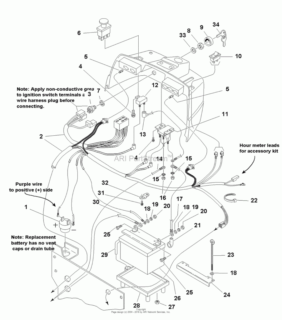
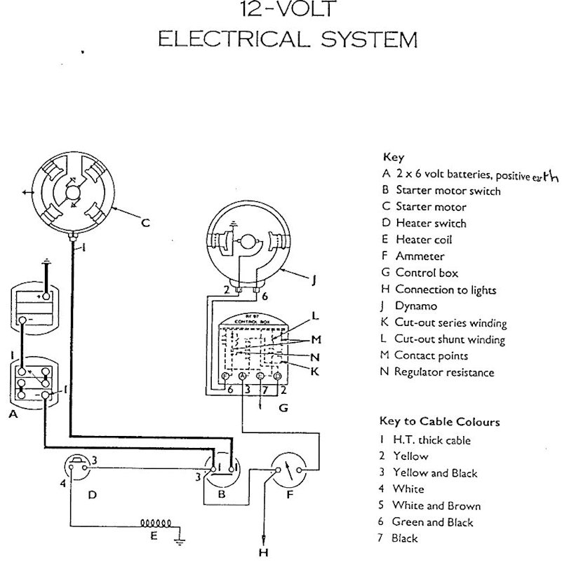
Gallery of Massey Ferguson Tractor Ignition Switch Wiring Diagram
Gallery of Massey Ferguson Tractor Ignition Switch Wiring Diagram


