Hotwire Bypass Ford Ignition Switch Wiring Diagram – Let’s start by looking at the different kinds of terminals that are found in an ignition switch. These terminals serve for the Ignition button, Coil and Accessory. After we’ve identified what these terminals are then we can determine the various components in the ignition wiring. In addition, we will discuss the function of the Ignition switch and Coil. Next, we’ll discuss the functions of the ignition switch and Coil.
Terminals for the ignition switch
An ignition switch is made up of three switches. These are the ones that supply the battery’s power to several locations. The ON/OFF setting of the ignition switch is controlled by the third switch, which supplies power to the choke when it’s pulled. Different manufacturers use their own color-coding systems for different conductors which is documented in another article. OMC utilizes this procedure. The ignition switch comes with an option to connect a timer.
Although many ignition switch terminals don’t appear in their original configuration, the numbering may not match the diagram. Check the continuity of the wires to ensure that they are plugged into the correct ignition switch. This can be accomplished using a simple multimeter. After you’re sure that the wires are in good continuity then you can connect the new connector. The wiring loom of an ignition switch that is supplied by the factory will be different from the one that you have in your car.
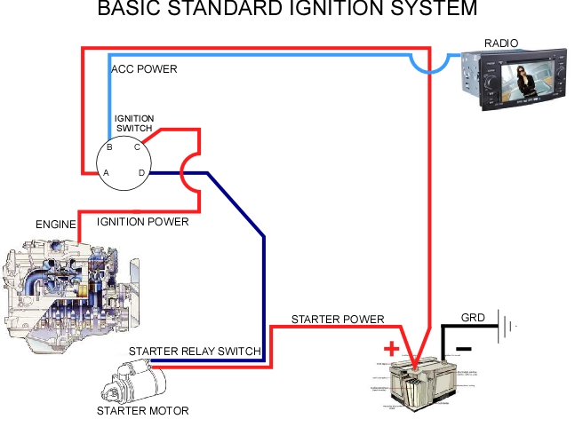
Understanding how ACC outputs connect to the other outputs of your car is essential. The ACC terminals as well as the IGN terminals serve as the default connections to your ignition switch. The START and IGN connections are the main connections for radio and stereo. The ignition switch turns the car’s engine ON and OFF. The terminals of older cars ignition switches are marked with “ACC” and ST (for individual magneto wires).
Terminals for coil
Understanding the terminology is the first step to knowing what type of ignition coil you own. A basic ignition wiring layout will show you a number of terminals and connections. You need to determine the kind of coil you have by testing the voltage on the primary terminal, called S1. S1 should also undergo resistance testing to determine whether it’s an A or B coil.
The chassis’ negative should be connected to to the coil’s lower-tension end. This is what’s called the ground in the wiring diagram for ignition. The high-tension part supplies positive direct to the sparkplugs. The aluminum body of the coil needs to be linked to the chassis for suppression however it’s not electrically required. The wiring diagram will depict the connection between positive and negative coils. It is possible to find an issue with your ignition coil which can be identified by scanning it in an auto parts retailer.
The black-and-white-striped wire from the harness goes to the negative terminal. The positive terminal is connected to the white wire with an trace of black. The contact breaker is connected to the black wire. To verify the connections, you can use a paperclip or a pencil to pull them out from the plug housing. Also, make sure to check that the terminals haven’t been bent.
Accessory terminals
The ignition wiring diagrams illustrate the various wires used to power the car’s various parts. Each component has four distinct connections that are color coded. Red is for accessories, yellow is for the battery, while green is the starter solenoid. The “IGN terminal allows you to start the car, manage the wipers or other functions. This diagram shows how to connect ACC and ST terminals with the rest of components.
The terminal BAT connects the battery to the charger. The electrical system will not start if the battery isn’t connected. Furthermore, the switch won’t start. A wiring diagram can inform you where to find your car’s battery. The ignition switch is linked to the car’s battery. The BAT terminal is connected with the battery.
Some ignition switches feature the “accessory” position that permits users to control their outputs without having to use the ignition. Sometimes, a customer wants to utilize the auxiliary output separately from the ignition. The auxiliary output is used to connect the connector in the same color as your ignition, and then attaching it to the ACC terminal of the switch. While this is an excellent feature, there’s something you need to know. A lot of ignition switches can be set to have an ACC location when the car has moved into the ACC position. They will also be in the START position once the vehicle is moved into the IGN position.
Gallery of Hotwire Bypass Ford Ignition Switch Wiring Diagram

Gallery of Hotwire Bypass Ford Ignition Switch Wiring Diagram


