Johnson Outboard Ignition Switch Wiring Diagram – The first step is to examine the various terminals on the ignition switch. These terminals are used for the Ignition button, Coil and Accessory. After we’ve identified the purpose of these terminals and what they do, we can then be able to identify the various parts of the ignition wiring. In addition, we will discuss the functions of the Ignition switch and Coil. After that, we will focus on the accessory terminals.
The terminals are for ignition switches.
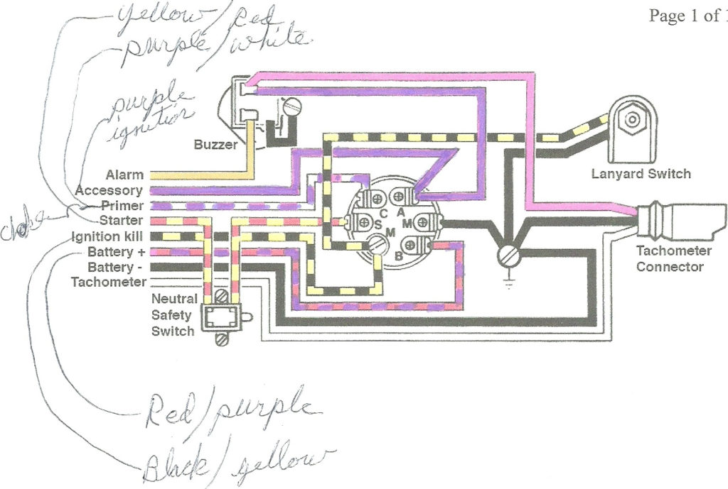
The ignition switch consists of three different switches. They are responsible for feeding the battery’s power to several destinations. The first switch provides power to the choke, while the second toggles the ON/OFF status of the ignition switch. Each manufacturer has their own color-coding system, which we’ll discuss in a subsequent article. OMC uses this method. There is a connector inside the ignition switch to allow attaching an to a tachometer.
While most ignition switch terminals are not original, the numbers for each may not match the diagram. It is important to first verify the continuity of the wires to determine if they’re connected to the ignition switch in the correct way. You can do this with an inexpensive multimeter. After you’ve confirmed that the wires are in good condition, you are able to install the connector. If your car is equipped with an original ignition switch supplied by the factory (or wiring loom), the wiring loom may differ from that in your vehicle.
First, understand the differences between the ACC and auxiliary outputs. The ACC and IGN terminals are the default connections for your ignition switch. the START and IGN terminals are the principal connections for radio and stereo. The ignition switch’s function is to turn the car’s engines on and off. The terminals for the ignition switch on older cars are labeled with the letters “ACC” and “ST” (for individual magneto wires).
Terminals for coil
Understanding the terminology that is used is the first step in determining what type of ignition coil. You will see several connections and terminals in an ignition wiring schematic, including two primary, as well as two secondary. The coils come with a distinct operating voltage, and the first method of determining what type you’ve got is to check the voltage on S1, the main terminal. S1 should be checked for resistance to determine if the coil is type A, B or C.
The chassis’ negative end should be connected to connect to the coil’s lower-tension end. This is the wiring diagram you will find in the wiring diagram. The high-tension supply delivers positively directly to spark plugs. The coil’s metal body needs to connect to the chassis for suppression purposes but is not electrically required. A wiring diagram can also depict the connection between positive and negative coil terminals. In certain instances scanning your local auto parts shop will be able to diagnose the malfunctioning ignition coils.
The black-and-white-striped wire from the harness goes to the negative terminal. Positive terminal receives the white wire that includes a black trace. The black wire connects to the contactbreaker. You can take the black wire from the plug housing with a paper clip if you are unsure about the connection. Be sure that you don’t bend the connectors.
Accessory terminals

The ignition wiring diagrams show the different wires used for powering the different components. Typically, there are four different colored terminals for each part. The red color represents accessories, yellow represents the battery, and green for the starter solenoid. The “IGN terminal” is used to provide power to the wipers and other operating functions. The diagram demonstrates how to connect the ACC and ST terminals to the rest of the components.
The battery is attached to the terminal named BAT. The electrical system will not start without the battery. The switch won’t turn on if the battery isn’t present. The wiring diagram will inform the location of the battery of your car. The accessory terminals of your vehicle are connected to the battery and the ignition button. The BAT terminal is connected to the battery.
Certain ignition switches come with the “accessory” position that permits users to regulate their outputs without having to use the ignition. In some cases, users may want to use the auxiliary input independently of the ignition. To make use of the auxiliary output, connect the connector using the same colors as ignition and connect it to the ACC terminal on the switch. This convenience feature is great however, there’s one difference. The majority of ignition switches are set up to show an ACC status when the vehicle is in the ACC or START positions.
Gallery of Johnson Outboard Ignition Switch Wiring Diagram
Gallery of Johnson Outboard Ignition Switch Wiring Diagram


