Husqvarna Ignition Switch Wiring Diagram – We will first look at the different types of terminals found in the ignition switch. These terminals include the Ignition switch, the Coil as well as the Accessory. Once we’ve determined the function of these terminals, we can determine the various components of the ignition wiring. We’ll also discuss the function of the Ignition switch, and Coil. We will then focus on the accessory terminals.
Terminals for the ignition switch
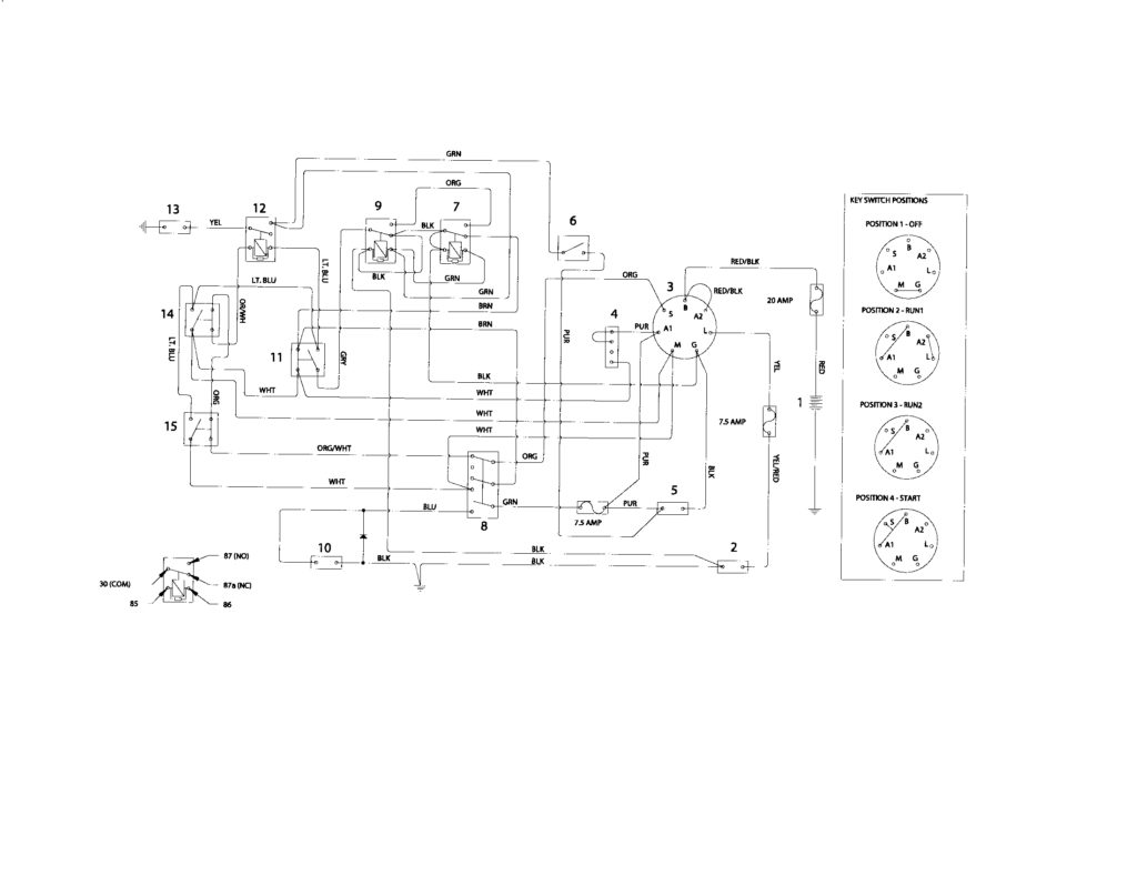
Three switches are located on an ignition switch. Each of these switches feeds the battery’s voltage to various places. The choke is powered by the first switch. The second switch controls the ON/OFF function of the ignition switch. Different manufacturers utilize their own color-coding method for different conductors which is documented in another article. OMC follows the same system. This connector allows the connection of a speedometer to the ignition switch.
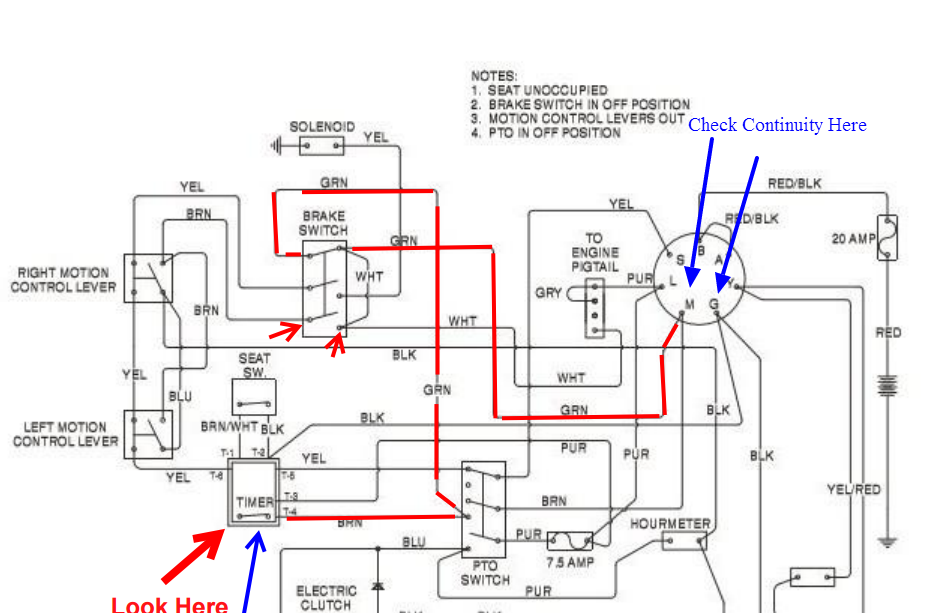
While many ignition switch terminals do not come in original form, the numbering may not match the diagram. Before plugging into the ignition switch ensure that you check the continuity. A multimeter that is inexpensive can aid in this. After you have verified the continuity of the wires you can then connect the connector. If your car has an installed ignition switch the wiring diagram will differ.
You must first understand the way that ACC outputs and the auxiliary outputs work in order to connect them. The ACC, IGN and START terminals are the default connection to the ignition switch. They also function as the primary connections to the radio and stereo. The ignition switch switches the car’s engine ON and off. On older cars the terminals of the ignition switch are identified with the alphabets “ACC”, and “ST” (for individual magnet wires).
Terminals for coil
To figure out the type of ignition coil, the initial step is to learn the terminology. You will see several connections and terminals within the basic wiring diagram for ignition which includes two primary and two secondary. Each coil is equipped with a distinct operating voltage. To determine which type of coil you’ve got the first step is to determine the voltage at S1, the primary terminal. You should also examine S1 for resistance to determine if it’s an A or B coil.
The coil with low tension must be connected to the chassis’ less. This is what’s called the ground on the diagram of ignition wiring. The high-tension part connects the spark plugs to a positive. For suppression purposes the coil’s body metal must be connected with the chassis. This is not necessary to use electricity. There are also connections between the positive and the negative coil’s terminals on the diagram of the ignition wiring. In some cases it is possible to find the ignition coil is damaged and can be diagnosed with scans at an auto parts shop.
The black-and-white-striped wire from the harness goes to the negative terminal. The terminal that is negative is served by the black trace that’s joined to the white wire. The black wire connects to the contact breaker. You can take the black wire from the plug housing with a paper clip if you are unsure about the connection. Also, make sure that the connections aren’t bent.
Accessory terminals
The ignition wiring diagrams illustrate the various wires utilized to power the vehicle’s various components. There are usually four color-coded terminus for each component. Red is used for accessories while yellow is the battery, while green is for the starter solenoid. The “IGN” terminal allows you to start your car, operate the wipers or other functions. The diagram below illustrates how to connect the ACC terminal and ST terminals to various components.
The battery is connected to the terminal whose name is BAT. The battery is necessary for the electrical system to begin. The switch also won’t turn on without the battery. If you’re not sure the exact location where the battery in your car is located, you can look at the wiring diagram of your car to determine how to locate it. The accessory terminals in your car are connected to the battery as well as the ignition button. The BAT connector is connected to the battery.
Some ignition switches have the “accessory” setting that allows users to control their outputs without having to use the ignition. Some customers may prefer to use the auxiliary output independently of the ignition. You can use the secondary output by connecting it to an ACC terminal on the switch with the same colors. This is a great option, but there’s an important difference. A lot of ignition switches can be programmed to have an ACC position when the vehicle is in the ACC position. They will also be in the START mode once the vehicle is moved into the IGN position.
Gallery of Husqvarna Ignition Switch Wiring Diagram
Gallery of Husqvarna Ignition Switch Wiring Diagram


