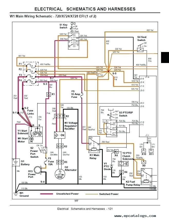
John Deere Ignition Switch Wiring Diagram – We will first examine the different types of terminals that are used on the ignition switch. These are the terminals that connect the Ignition, Coil, or Accessory. Once we’ve established the purpose of the terminals we can determine the various components of the ignition wiring. We will also talk about the functions and the Coil. Following that, we will move on to the Accessory Terminals.
The terminals are for ignition switches.
An ignition switch has three switches that supply the battery’s power to various destinations. The first switch is the one that supplies power to the choke, while the second toggles the status of the ignition switch. Each manufacturer has their own color-coding system, which we will discuss in another article. OMC follows this scheme. The adapter is attached to the ignition switch to allow the installation of an tonometer.
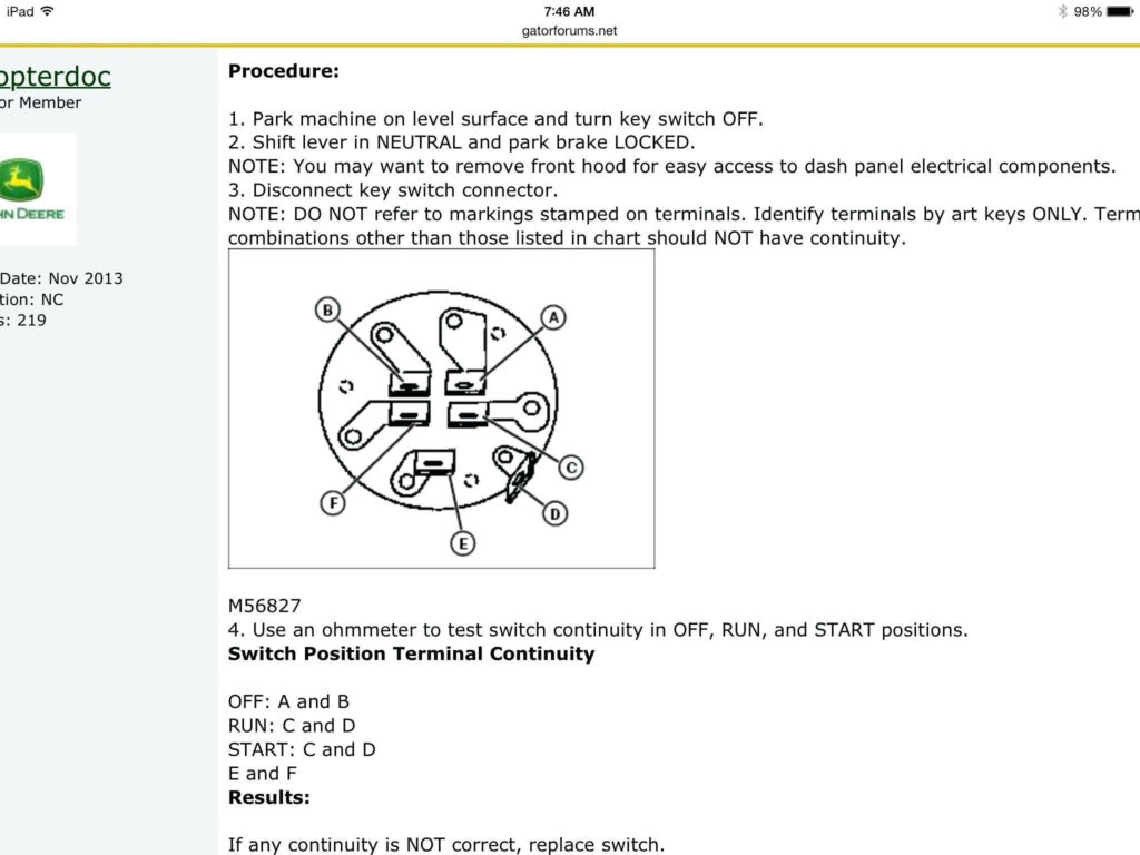
Although some ignition switch terminals may not be original, the numbering of the terminals may not be in line with the diagram. Check the electrical continuity first to ensure they’re connected correctly to the ignition switch. This can be accomplished with a simple multimeter. After you’re sure that all wires are running in good harmony then you can connect the new connector. If you have an ignition switch that is supplied by the manufacturer the wiring loom may be distinct from the one that is you have in your car.
First, understand the differences between ACC and the auxiliary outputs. The ACC/IGN connections function as the default connections on the ignition switch. The START/IGN terminals are connected to the radio or stereo. The ignition switch acts as the engine’s switch to turn off or on. The terminals on older cars ignition switches are identified with “ACC” as well as ST (for individual magneto wires).
Terminals for coil
The first step in determining the kind of ignition coil is to comprehend the terms used. In a simple diagram of the wiring for ignition you’ll see several different connections and terminals, such as two primary and two secondary. The coils are equipped with a particular operating voltage. The first method of determining what type you have will involve testing the voltage on S1, the primary terminal. Also, you should test S1 for resistance in order to determine whether it is a Type A or B coil.
The chassis’ negative end should be connected to connect the coil’s low-tension end. This is what’s called the ground in the diagram of the ignition wiring. The high-tension component supplies positively direct to the spark plugs. To reduce the noise the coil’s metal body is required to be connected to the chassis. It is not required to use electricity. The wiring diagram for ignition will also outline the connection of the positive coil terminals. In some cases it is recommended to conduct a scan at your local auto parts store will help identify defective ignition coils.
The black-and-white-striped wire from the harness goes to the negative terminal. The white wire is black-colored and goes to the negative terminal. The contact breaker is connected to the black wire. You can take the black wire from the housing of the plug using a paper clip If you’re unsure of the connections. Make sure that the terminals do not bend.
Accessory terminals
Ignition wiring diagrams show the different wires that are utilized to power the vehicle’s various parts. In general there are four colors-coded terminals that are used for each component. Red stands for accessories, yellow for the battery and green for the starter solenoid. The “IGN terminal is used to start the vehicle, controlling the wipers, and for other functions. The diagram illustrates how to connect ACC or ST terminals, and other.
The terminal referred to as BAT is the location where the battery is. The electrical system will not start if the battery isn’t connected. Furthermore the switch isn’t turned on. It is possible to look up the wiring diagram of your car to see where the batteries of your car are situated. The ignition switch is linked to the car’s battery. The BAT Terminal is connected to the battery.
Some ignition switches come with an independent “accessory” position, where users can control their outputs without the ignition. In some cases, users may want to utilize the auxiliary output separately from the ignition. To make use of the auxiliary output, connect the connector with the same colors as the ignition and connect it to the ACC terminal on the switch. This is a great convenience feature, but there is one distinction. Most ignition switches are configured to have an ACC position when the vehicle is in the ACC position, whereas they’re set to the START position when the vehicle is in the IGN position.
Gallery of John Deere Ignition Switch Wiring Diagram
Gallery of John Deere Ignition Switch Wiring Diagram


