Hz Holden Ignition Switch Wiring Diagram – Let’s first examine the different kinds and functions of terminals that are found on the ignition switches. They include terminals for Coil, Ignition Switch, and Accessory. Once we know the purpose of these terminals then we can identify the different parts in the ignition wiring. We will also cover the different functions of the Ignition Switch and Coil. Following that, we’ll shift our attention to Accessory terminals.
Terminals for ignition switches
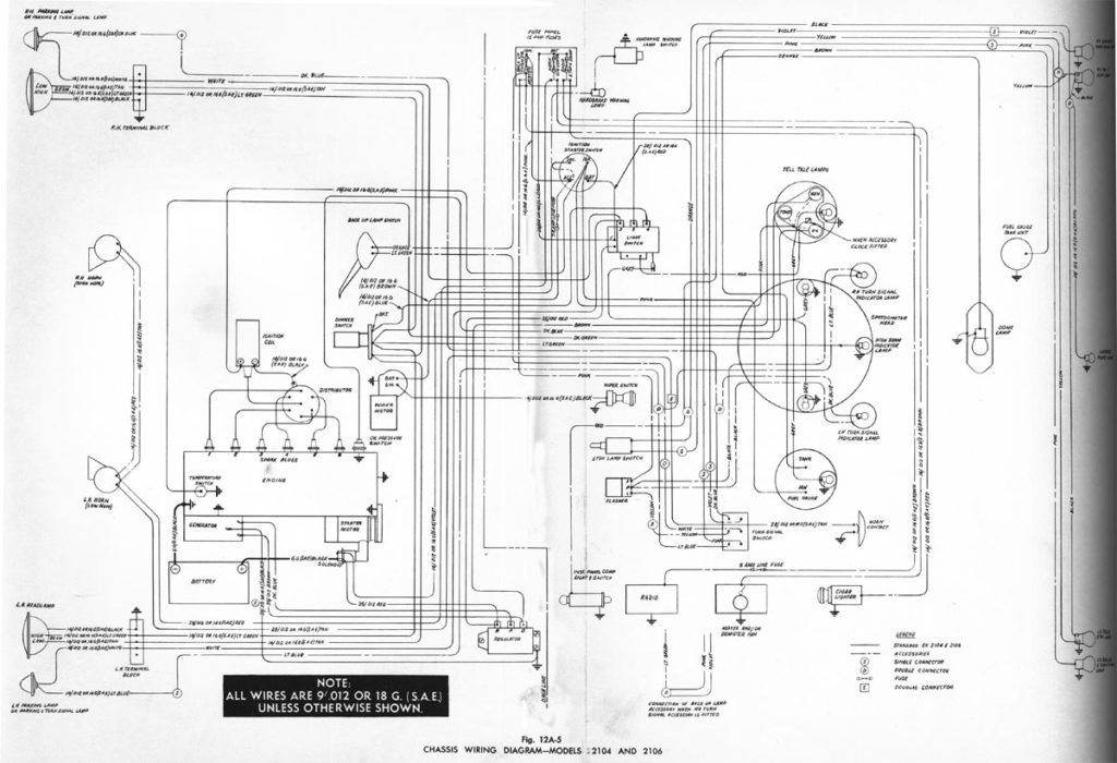
An ignition switch has three separate switches that feed the battery’s current to different locations. The first switch powers the choke. The second switch controls the ON/OFF function of the ignition switch. Different manufacturers employ various color codes for the different conductors. This is discussed in another article. OMC follows this method. Connectors can be connected to the ignition switch in order to add the digital tachometer.
While most ignition switch terminals are duplicated, the numbers might not be consistent with the diagram. The first step is to check the continuity of all the wires to make sure they’re properly plugged into the ignition switches. This can be checked using a cheap multimeter. Once you’re satisfied about the continuity of the wires, then you’ll be able to install the new connector. The wiring loom of a factory-supplied ignition system switch is distinct.
It is essential to know the way that ACC outputs and the auxiliary outputs function in order to join them. The ACC and IGN connectors are the default connections for the ignition switch. While the START, IGN, and ACC terminals are primary connections to the radio or stereo, the START/IGN terminals are the most important ones. The ignition switch is the one that controls the engine of your car. The terminals for the ignition switch on older cars are identified with the alphabets “ACC” and “ST” (for individual magneto wires).
Terminals for coil
Understanding the terms utilized is the initial step to determining what kind of ignition coil to choose. The fundamental diagram of ignition wiring illustrates a variety of connections and terminals. There are two primary and one secondary. The coils are equipped with a particular operating voltage, and the first step in determining which type you’ve got is to check the voltage on S1, the primary terminal. S1 should be examined for resistance to determine if the coil is Type A, B, and/or C.
The low-tension coil side must be connected to the chassis’s less. This is the ground of the wiring for ignition. The high-tension side supplies positive directly to the spark plugs. The metal body of the coil needs to be connected to the chassis for suppression purposes but is not electrically required. It is also possible to see the connections between the positive and the negative coil terminals on the diagram of the ignition wiring. There could be an ignition coil problem which can be identified by scanning it at an auto parts store.
The black-and-white-striped wire from the harness goes to the negative terminal. The other white wire is black-colored and connects to the terminal opposite. The contact breaker is linked to the black wire. To verify the connection, employ a paperclip, or a pencil to pull them out of the plug housing. Make sure the terminals aren’t bent.
Accessory terminals
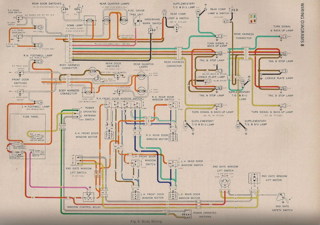
The diagrams for ignition wiring illustrate the wires used to power the vehicle’s electrical supply. There are typically four colored terminals that correspond to the component. Red is for accessories, yellow is for the battery, and green is the solenoid for starters. The “IGN” terminal can be used to start the car, turn on the wipers and other functions. The diagram shows how to connect the ACC and ST terminals to the rest of the components.
The terminal BAT is where the battery is. The electrical system will not start when the battery isn’t connected. Additionally, the switch won’t start. You may refer to the wiring diagram if uncertain about where the car’s batteries are. The accessory terminals of your car are connected to the ignition switch as well as the battery. The BAT terminal is connected with the battery.
Certain ignition switches have an accessory position. It allows users to access their outputs from a different location without having to turn on the ignition. Sometimes, customers would like an auxiliary output that can be used separately from the ignition. To make use of the additional output, wire the connector with the same colors as ignition and connect it to the ACC terminal on the switch. Although this is a fantastic feature, there’s one thing you need to know. Most ignition switches are set to operate in the ACC position when the car is in the ACC position, but they’re in the START position when the vehicle is in the IGN position.
Gallery of Hz Holden Ignition Switch Wiring Diagram
Gallery of Hz Holden Ignition Switch Wiring Diagram


