Third Gen Camaro Ignition Wiring Diagrams – We’ll begin by looking at the various types of terminals on an ignition switch. These are terminals for the Ignition, Coil, or Accessory. After we’ve identified the terminals that are utilized then we can recognize the various parts of the Third Gen Camaro Ignition Wiring Diagrams. In addition, we will discuss the functions of the Ignition switch and Coil. We’ll then turn our attention to the accessory terminals.
The terminals are for ignition switches.
Three switches are found on the ignition switch. Each of the three switches is able to feed the battery’s voltage to several different locations. The first one is used to power the choke by pushing it, and another switch controls the ON/OFF setting. Different manufacturers have distinct colour-coding systems that correspond to the conductors. OMC utilizes this procedure. This connector allows the attachment of a speedometer the ignition switch.
Although some ignition switch terminals could not be original, the numbering of the terminals may not match the diagram. Before you plug in the ignition switch, make sure to check the continuity. A simple multimeter will aid in this. When you’re satisfied with the continuity of your wires, you’ll be able install the new connector. The wiring loom of an ignition switch that is factory-supplied will be different than the one you have in your car.
To connect the ACC outputs to the auxiliary outputs of your car, you need first know the way these two connections function. The ACC and IGN terminals are the default connections for your ignition switch, and the START and IGN terminals are the main connections to the radio and stereo. The ignition switch is the one that controls the engine of your car. The terminals of older cars ignition switches are marked with “ACC” and ST (for specific magneto wires).
Terminals for coil
Understanding the terminology is the first step to finding out what kind of ignition coil you’ve got. You will see several connections and terminals within the basic wiring diagram for ignition, including two primary, as well as two secondary. The coils are equipped with a particular operating voltage, and the first step in determining which type you have will involve testing the voltage at S1, the main terminal. To determine whether it’s an A, C, or B coil, you should also test the resistance on S1’s.
The coil’s low-tension side should be connected to the chassis’s plus. This is the wiring diagram you will see in the diagram of wiring. The high tension side supplies positive directly the spark plugs. The metal body of the coil needs to be connected to the chassis for suppression purposes, but it is not electrically essential. The wiring diagram of the ignition will demonstrate how to connect the two terminals of the positive and negative coils. In some instances you’ll discover that an ignition coil that is malfunctioning is easily identified with scans at an auto parts shop.
The black-and-white-striped wire from the harness goes to the negative terminal. The positive terminal is connected to the white wire, which has the trace in black. The contact breaker is attached to the black wire. It is possible to remove the black wire from the housing of the plug by using a paperclip if you are unsure about the connections. Also, make sure to ensure that the terminals haven’t been bent.
Accessory terminals
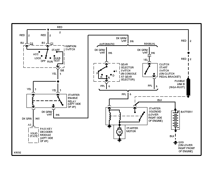
The wiring diagrams for the ignition show the different wires that provide power to the various parts of the car. There are typically four color-coded terminals that correspond to the component. Red is used for accessories, yellow is for the battery, while green is the starter solenoid. The “IGN” terminal is used to start the car, operating the wipers, and for other functions. The diagram illustrates how you can connect ACC or ST terminals, and other.
The terminal BAT connects the battery to the charger. Without the battery the electrical system will not begin. The switch won’t be able to turn on if there is no battery present. To locate your car’s battery examine the wiring diagram. The accessory terminals on your car are connected to the battery as well as the ignition switch. The BAT terminal connects to the battery.
Some ignition switches are equipped with an accessory position. This allows users to connect their outputs to a different location without having to turn on the ignition. Some customers prefer to utilize an additional output independent of the ignition. For the auxiliary output to be used, plug in the connector to the same color as that of the ignition. Then connect it with the ACC end of the switch. This is an excellent option, but there’s an important difference. The majority of ignition switches are configured to show an ACC status when the vehicle is at either the ACC or START position.
Gallery of Third Gen Camaro Ignition Wiring Diagrams
Gallery of Third Gen Camaro Ignition Wiring Diagrams


