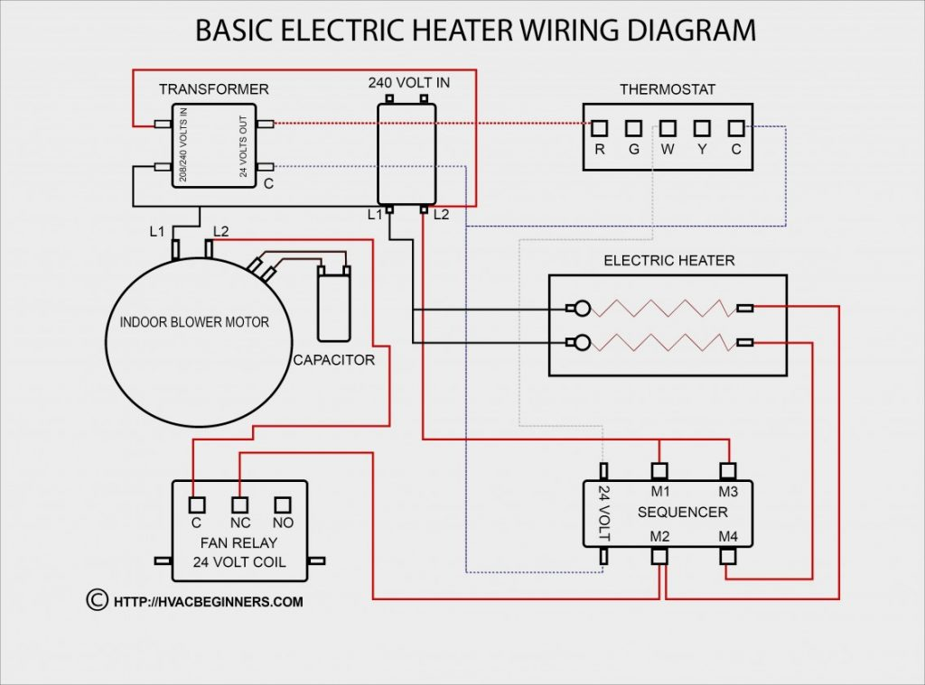
Ignition Coil Condenser Wiring Diagram – We will first examine the different types of terminals for the ignition switch. They include terminals for Coil, Ignition Switch, and Accessory. Once we have identified what these terminals do then we can be able to identify the various parts of the ignition wiring. We will also discuss what functions are available for the Ignition switch and the Coil. After that, we’ll turn our attention to Accessory terminals.
The terminals of the ignition switch
There are three different switches in the ignition switch, and they transmit the battery’s current voltage to various locations. The choke is powered by the first switch. The second switch is responsible for the ON/OFF function of the ignition switch. Different manufacturers use different color-coding methods for different conductors. We will cover this in another article. OMC follows this procedure. An adapter is included on the ignition switch to allow the addition of an Tachometer.
Although most ignition switch terminals are duplicated, the numbers may not be in line with the diagram. To make sure that the wires are correctly connected to the switch, you must verify their continuity. A multimeter is an excellent instrument to verify the continuity. After you’re satisfied with the integrity of the wires it is time to install the new connector. If your vehicle is equipped with an ignition switch installed, the wiring diagram will differ.
Before you can connect the ACC outputs to your car’s auxiliary outputs It is essential to know the fundamentals of these connections. The ACC and IGN terminals are the default connection on your ignition switch, and the START and IGN terminals are the primary connections for the stereo and radio. The ignition switch switches the car’s engine ON and off. Older cars are equipped with ignition switch terminals marked “ACC” or “ST” (for individual magnetowires).
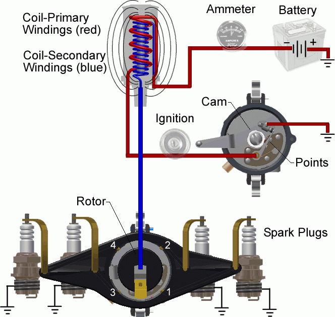
Terminals for coil
To identify the kind of ignition coil, the first step is to know the terms. A basic ignition wiring diagram will show a variety of connections and terminals, including two primary and two secondary. Each coil operates at a specific voltage. The first step to determine which type you’re dealing with is to test the voltage at S1 or the primary terminal. S1 must also go through resistance tests to determine if it are a Type A or B coil.
The chassis’ negative should be connected to the coil’s low-tension end. This is also the ground in the diagram of ignition wiring. The high-tension component supplies the positive power direct to the spark plugs. It is necessary to suppress the body of the coil’s metal be connected to the chassis, however it isn’t essential. The ignition wiring diagram will also demonstrate the connection of the positive and negative coil terminals. Sometimes, a defective ignition coil is identified with a scan at an auto repair shop.
The black-and-white-striped wire from the harness goes to the negative terminal. The positive terminal also receives the white wire that has a black trace. The black wire connects to the contact breaker. To test the wires’ connections, employ a paperclip to remove them off the housing. Make sure the terminals aren’t bent.
Accessory terminals
Diagrams of the ignition wiring illustrate the wiring used to supply power to different parts of the vehicle. There are usually four different color-coded terminals to each component. To identify accessories, red stands for starter solenoid, yellow for battery, and blue for accessory. The “IGN” terminal can be used to start the car, operate the wipers, as well as other functions. The diagram shows how to connect the ACC and ST terminals to the other components.
The terminal called BAT is the location where the battery is. Without the battery, the electrical system does not start. Furthermore, the switch doesn’t turn on. To locate your car’s battery examine the wiring diagram. The ignition switch is connected to the battery of your car. The BAT connector is connected to your battery.
Some ignition switches come with an additional “accessory position” that lets users adjust their outputs independently of the ignition. Customers sometimes want the output of the auxiliary to be used separately from the ignition. For the auxiliary output to be used, wire the connector to the same color as the ignition. Then , connect it to the ACC end of the switch. This feature of convenience is fantastic however there’s a difference. A majority of ignition switches feature the ACC position when your car is in the ACC mode and a START position when you are in IGN.
Gallery of Ignition Coil Condenser Wiring Diagram
Gallery of Ignition Coil Condenser Wiring Diagram


