1974 Vw Beetle Ignition Switch Wiring Diagram – First, let’s examine the various terminals used on the ignition switch. These terminals comprise the Ignition switch and Coil along with the Accessory. Once we’ve determined the function of these terminals, we will be able to identify the various parts of the ignition wiring. Then, we will discuss the roles of the Ignition switch as well as the Coil. Then, we’ll turn our attention to Accessory terminals.
Terminals for ignition switches
An ignition switch has three switches. They feed the battery’s voltage to different places. The first switch provides power to the choke whenever it is pushed. The third is the position of the ignition switch’s ON/OFF. Different manufacturers use their own color-coding systems for the various conductors, which is explained in a different article. OMC uses the same method. A connector can be added to the ignition switch to add the digital tachometer.
Although some ignition switch terminals do not have the original design The numbering might not match the diagram. Before you plug into the ignition switch, make sure to check the continuity. You can do this with an inexpensive multimeter. When you’re satisfied with the continuity of your wires, you’ll be able to install the new connector. If your car has an original ignition switch supplied by the factory (or a wiring loom) the wiring loom will differ from that of the car.
Before you can connect the ACC outputs to the auxiliary outputs of your car it is crucial to know the fundamentals of these connections. The ACC, IGN and START terminals are the primary connection to the ignition switch. They also serve as the primary connections to your radio and stereo. The ignition switch operates the engine’s on/off button. Older cars have the ignition switch terminals labeled “ACC” or “ST” (for individual magnetowires).
Terminals for coil
To determine the type of ignition coil, the initial step is to understand the terminology. In a simple ignition wiring diagram, you will see a number of different connections and terminals, which include two primary and two secondary. It is essential to identify the kind of coil you have by testing the voltage on the primary terminal, called S1. S1 should be checked for resistance to determine if the coil is Type A, B, or C.
The negative of the chassis must be connected to the side of low-tension. This is also the ground on the ignition wiring diagram. The high-tension component provides the spark plugs with positive. To reduce the noise, the coil’s metal body must be connected to the chassis. However, it is not necessary to electrically connect. The wiring diagram of the ignition will demonstrate how to connect the terminals of either the positive and negative coils. In some cases it is possible to find the ignition coil is damaged and is easily identified with scans in an auto parts store.
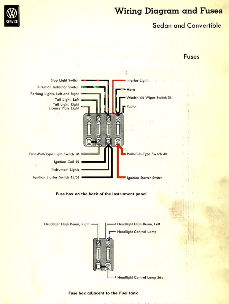
The black-and-white-striped wire from the harness goes to the negative terminal. Positive terminal receives the white wire that includes a black trace. The black wire connects with the contact breaker. If you’re not sure about the connection between the two, try using an old paper clip to take them from the plug housing. Also, make sure to check that the terminals aren’t bent.
Accessory Terminals
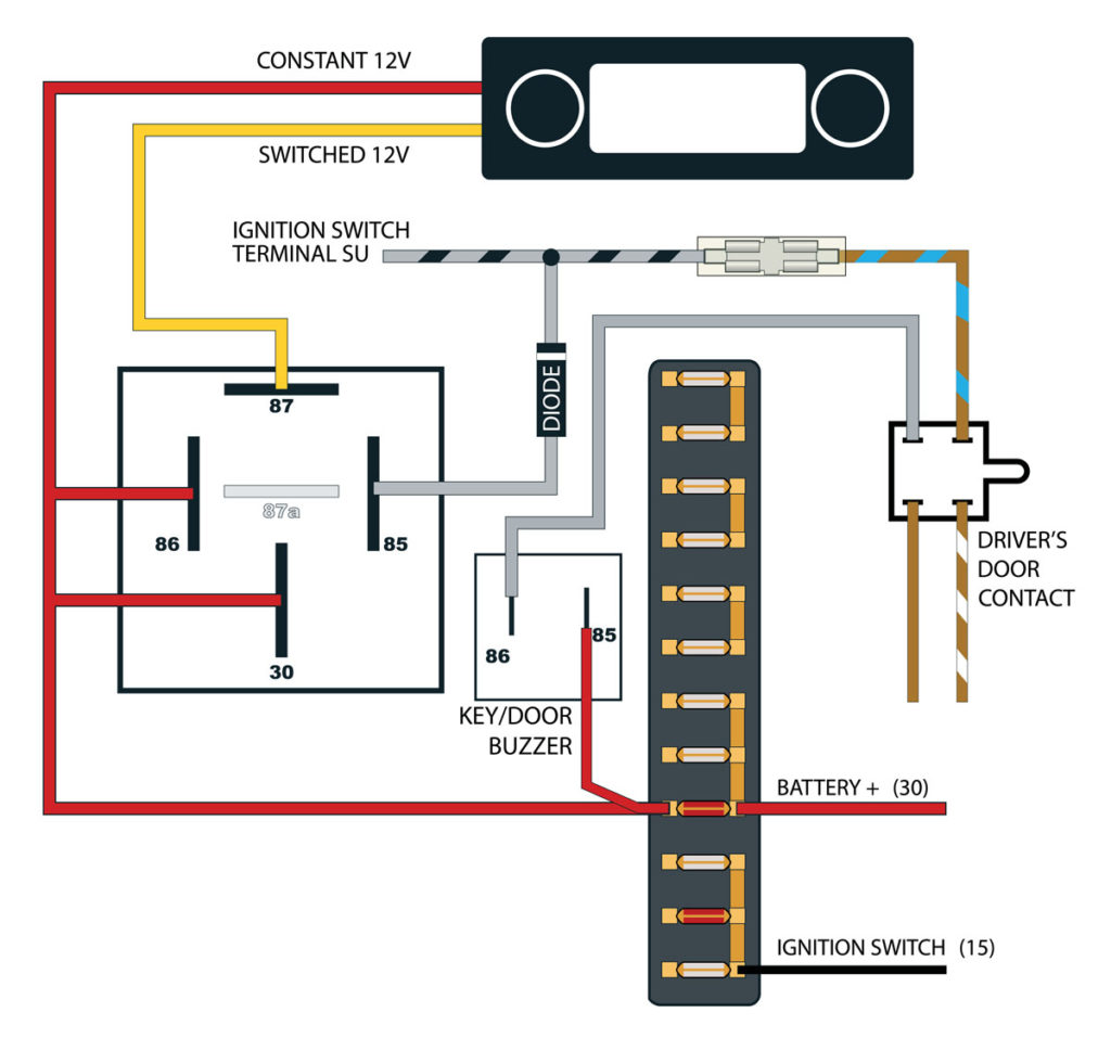
The ignition wiring diagrams illustrate the different wires used to are used to power various components of the vehicle. There are usually four colored terminus lines for each component. Red is used for accessories and yellow is for the battery, while green is the starter solenoid. The “IGN” terminal is used to start the car, operating the wipers, and for other functions. The diagram illustrates how to connect ACC or ST terminals and the rest.
The terminal known as BAT is the place where the battery is. Without the battery the electrical system can not start. The switch will not turn on if the battery isn’t present. If you’re not sure of the location of your car’s battery located, you can examine your wiring diagram to see the best way to find it. The ignition switch as well as the battery are connected by the accessory terminals. The BAT terminal is connected to the battery.
Some ignition switches offer the option of an “accessory position” which allows users to alter their outputs without the ignition. Sometimes, customers want to utilize an auxiliary output that is separate from the ignition. It is possible to use the additional input by connecting it to the ACC terminal. This feature of convenience is fantastic, but there is one distinction. A lot of ignition switches can be configured to be in an ACC position once the car has moved into the ACC position. They also will be in the START mode when the vehicle has moved into the IGN position.
Gallery of 1974 Vw Beetle Ignition Switch Wiring Diagram
Gallery of 1974 Vw Beetle Ignition Switch Wiring Diagram


