Harley Evo Ignition Wiring Diagram – Let’s begin by examining the different types and purposes of the terminals found in the ignition switches. They include terminals for the Ignition switch, Coil, and Accessory. After we’ve identified the purpose of these terminals then we can determine the various components in the ignition wiring. We’ll also discuss the functions and the Coil. Following that, we’ll shift our attention to Accessory terminals.
Terminals for ignition switch
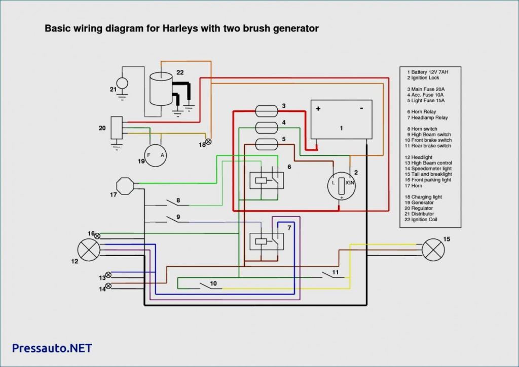
An ignition switch has three switches. They supply the battery’s voltage to many different locations. The first switch is utilized to turn on the choke by pushing it. Then, the second is for the ON/OFF setting. Different manufacturers employ different color codes for different conductors. This is discussed in a different article. OMC utilizes this method. A tachometer adapter is installed on the ignition switch to allow the installation of a Tachometer.
While the majority of the ignition switch terminals may not be original, the numbering for each one may not be in line with the diagram. Before you plug into the ignition switch, make sure to check the continuity. A multimeter is a good tool to test the continuity. When you’re satisfied with the integrity of your wires, you’ll be able to install the new connector. If your vehicle has an installed ignition switch the wiring diagram will differ.
In order to connect the ACC outputs to the auxiliary outputs on your car, you’ll need first know the way these two connections function. The ACC and IGN terminals are the default connection on the ignition switch. the START and IGN terminals are the primary connections to the radio and stereo. The ignition switch’s function is for turning the car’s engine on and off. The terminals for the ignition switch on older cars are labeled with the alphabets “ACC” and “ST” (for the individual magneto wires).
Terminals for coil
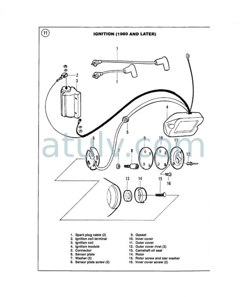
To determine the type of ignition coil you need to know the step is to understand the terminology. You’ll see a number of connections and terminals within a basic ignition wiring schematic, including two primary, and two secondary. The voltage that operates on every coil is different. Therefore, it is crucial to test the voltage at S1 (primary terminal). To determine if it is an A, C or B coil you should also check the resistance of S1.
The chassis’ negative must be connected to the side of low-tension. This is what is known as the ground for the wiring for ignition. The high-tension side supplies positive direct to the sparkplugs. The coil’s aluminum body needs to be connected to the chassis to prevent it from being smothered however it’s not electrically required. You will also see the connections of the positive and negative coil’s terminals on an ignition wiring diagram. In certain cases, a scan at the local auto parts store can help you identify defective ignition coils.
The black-and-white-striped wire from the harness goes to the negative terminal. The negative terminal is served by the black trace that’s connected to the white wire. The black wire connects to the contact breaker. You can examine the connections with a paperclip to pull the wires out of the housing. Make sure you verify that the connections have not been bent.
Accessory terminals
Diagrams of ignition wiring illustrate the wires that are used in the vehicle’s power supply. There are usually four different colors of terminals connected to each part. Red is used to indicate accessories, yellow is the battery, and green is the starter solenoid. The “IGN” terminal can be used to start the vehicle and control the wipers as well as other operational features. The diagram shows how to connect the ACC and ST terminals to the other components.
The terminal referred to as BAT is the place where the battery is. The electrical system will not start when the battery isn’t connected. Additionally, the switch will not turn on without the battery. It is possible to view your wiring diagram to figure out the location of your car’s batteries. situated. Your car’s accessory terminals connect to the ignition switch, as well as the battery. The BAT Terminal is connected to the Battery.
Some ignition switches have an “accessory” position that permits users to regulate their outputs without needing to utilize the ignition. Customers may want to use the auxiliary output separately from the ignition. In order to use the auxiliary output, wire the connector in identical colors to the ignition, and connect it to the ACC terminal on the switch. This is a useful option, but there’s one important distinction. A lot of ignition switches can be configured to be in an ACC position once the car has been moved into the ACC position. They’ll also be in the START mode when the vehicle has moved into the IGN position.
Gallery of Harley Evo Ignition Wiring Diagram
Gallery of Harley Evo Ignition Wiring Diagram


