1995 Ford F150 Ignition Switch Wiring Diagram – First, let’s examine the various terminals used on the ignition switch. These terminals serve for the Ignition button, Coil and Accessory. Once we understand the function of each terminal, we are able to identify the various components of the ignition wiring. In addition, we will discuss the functions of both the Ignition Switch and Coil. After that we will proceed to the Accessory Terminals.
Terminals of ignition switch
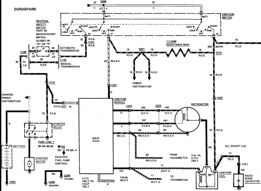
Three switches can be found on the ignition switch. Each of these three switches is able to feed the battery’s voltage to a variety of locations. The ON/OFF setting of the switch that controls the ignition is managed by the first switch, which provides power to the choke when it is pushed. Different manufacturers use their own color-coding systems for different conductors which is explained in a different article. OMC uses this method. There is a connector inside the ignition switch for attaching a to a tachometer.
Although the majority of ignition switch terminals are duplicated, the number may not be consistent with the diagram. Check the continuity of all wires to make sure they’re properly connected to the ignition switches. You can check this using a simple multimeter. When you’re happy with the continuity then you can connect the new connector. If your car has an original factory-supplied ignition switch (or wiring loom) The wiring loom might differ from that of your car.
Knowing how the ACC outputs are connected to the auxiliary outputs of your car is vital. The ACC and IGN connectors are the default connections of the ignition switch. While the START, IGN, and ACC terminals are primary connections for radios or stereo, the START/IGN connections are the most important ones. The ignition switch switches the car’s engine on and OFF. The ignition switch terminals on older cars are labeled with the letters “ACC” as well as “ST” (for the individual magneto wires).
Terminals for coil
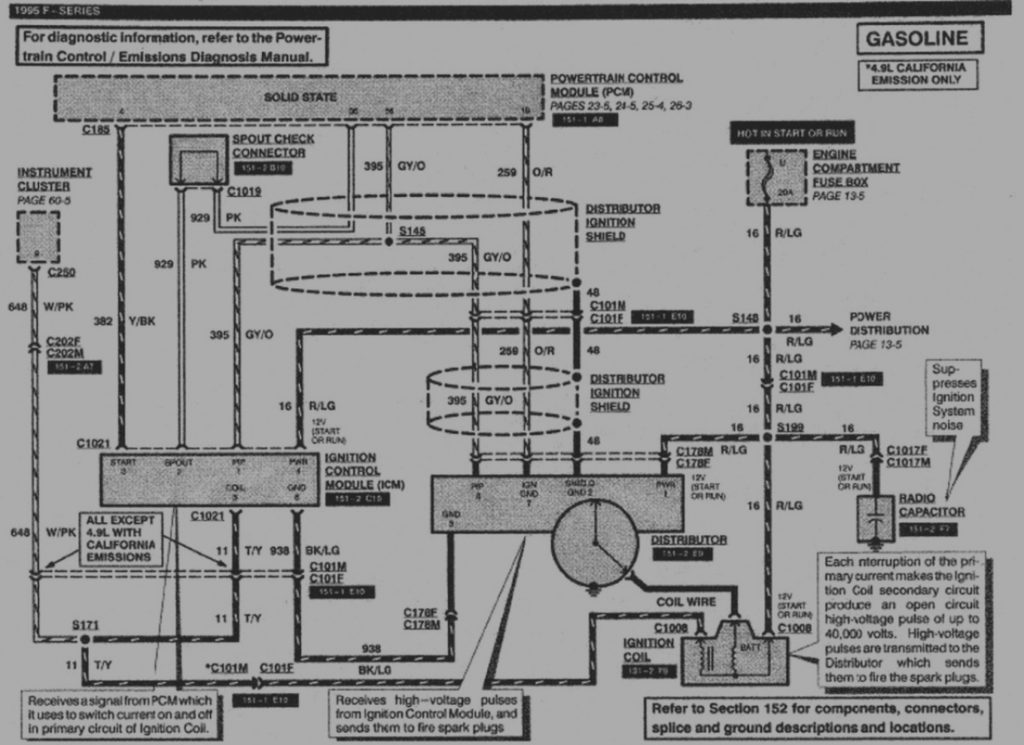
The first step in determining the kind of ignition coil is to understand the terminology that is used. An understanding of the basic wiring diagram for ignition will show you a number of connections and terminals. The coils come with a distinct operating voltage, and the first method of determining what type you’re using is to test the voltage on S1, the primary terminal. S1 should also undergo resistance tests to determine if it is a Type A or B coil.
The negative of the chassis must be connected to the low-tension side. This is the ground of the wiring for ignition. The high-tension side supplies the spark plugs with positive. To prevent noise the coil’s metal body must be connected to the chassis. It is not required for electrical use. The wiring diagram will show the connection between the positive and negative coils. In some instances, you’ll find that an ignition coil that is malfunctioning is easily identified with scanning in an auto parts store.
The black-and-white-striped wire from the harness goes to the negative terminal. The other white wire is black with a trace, and connects to the positive terminal. The black wire connects to the contactbreaker. To confirm the connection, employ a paperclip, or a pencil to lift them out of the housing for the plug. It’s also essential to make sure that the terminals do not bend.
Accessory terminals
The ignition wiring diagrams illustrate the different wires that are utilized to power the vehicle’s various components. Each component has four distinct connections that are color coded. The red color represents accessories, yellow for the battery, and green for the solenoid for starters. The “IGN” terminal is used to turn on the car and operate the wipers and other operating features. The diagram shows the connections of the ACCas well as ST terminals.
The terminal BAT connects the battery to the charger. The battery is necessary for the electrical system to get started. Additionally, the switch will not be able to turn on without the battery. A wiring diagram can tell the location of the battery of your car. The ignition switch is connected to the car’s battery. The BAT Terminal is connected to the battery.
Some ignition switches come with an accessory position. It allows users to access their outputs from a different place without the ignition. Sometimes, a customer wants to make use of the auxiliary output separately from the ignition. In order to use the auxiliary output, wire the connector with the same colors as ignition, and connect it to the ACC terminal on the switch. This is a great option, but there’s an important distinction. Most ignition switches are configured to operate in the ACC position when the car is in the ACC position, but they’re set to the START position when the vehicle is in the IGN position.
Gallery of 1995 Ford F150 Ignition Switch Wiring Diagram
Gallery of 1995 Ford F150 Ignition Switch Wiring Diagram


