Motorcycle Ignition Switch Wiring Diagram – We will first take a look at the different kinds of terminals on the ignition switch. These terminals are for the Ignition button, Coil and Accessory. Once we know the purpose of each type of terminal, we are able to identify the various components of the ignition wiring. We will also discuss the roles of the Ignition switch and Coil. Following that, we’ll shift our attention to the Accessory terminals.
Ignition switch terminals
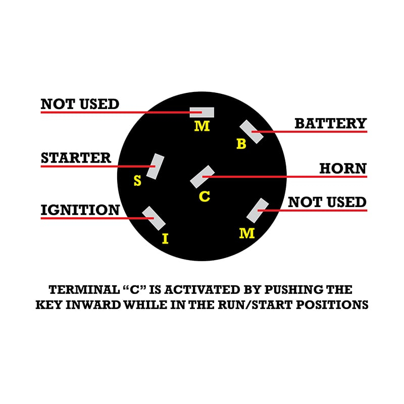
Three switches are found in an ignition switch. Each of these switches feeds the battery’s voltage to various places. The first is used to turn on the choke by pushing it. Then, another switch controls the ON/OFF setting. Each manufacturer has their individual color-coding system that we’ll go over in a separate article. OMC uses the same method. The connector permits the attachment of a speedometer to the ignition switch.
Even though some of the ignition switch terminals may not be original, the numbers of each one might not be in line with the diagram. To ensure that the wires are properly plugged in to the switch you must verify their continuity. This can be accomplished using an inexpensive multimeter. Once you are satisfied with the continuity of the wires it is time to connect the new connector. If you have an ignition switch supplied by the manufacturer, the wiring loom is distinct from the one that is used in your vehicle.
Before you can connect the ACC outputs to the auxiliary outputs of your car It is essential to know the fundamentals of these connections. The ACC/IGN terminals function as the default connections for the ignition switch. The START/IGN terminals connect to the stereo or radio. The ignition switch acts as the engine’s off/on button. The terminals of older vehicles’ ignition switches are labeled with “ACC” as well as ST (for the individual magneto wires).
Terminals for coil
To identify the kind of ignition coil, the first step is to learn the definition of. A basic ignition wiring layout will show you a number of terminals and connections. The operating voltage of each coil is different. It is crucial to test the voltage at the S1 (primary terminal). You should also examine S1 for resistance in order to determine whether it is a Type A, B, or C coil.
The chassis’ negative needs to be connected to the low-tension side. This is what you see on the diagram of wiring. The high tension side provides positive power directly to the spark plugs. For suppression purposes, the coil’s body metal must be connected with the chassis. It’s not necessary for electrical use. There are also connections of the negative and positive coil terminals on the ignition wiring diagram. Sometimes, a defective ignition coil can be detected with a scan in an auto parts shop.
The black-and-white-striped wire from the harness goes to the negative terminal. The negative terminal is served by the black trace joined to the white wire. The black wire connects to the contact breaker. You can check the connections with a pencil to pull the wires out from the housing. Be sure to ensure that the terminals haven’t been bent.
Accessory terminals
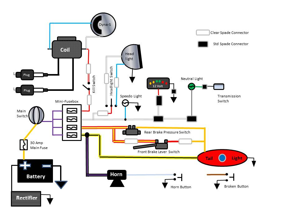
Diagrams of ignition wiring illustrate the wiring used in the vehicle’s power supply. There are usually four colored terminals that correspond to the component. To identify accessories, red stands for starter solenoid, yellow for battery, and blue for accessories. The “IGN terminal allows you to start the car, manage the wipers or other functions. The diagram below illustrates how to connect the ACC terminal as well as the ST terminals to other components.
The terminal BAT is the connection for the battery. The electrical system won’t start in the event that the battery isn’t connected. Additionally, the switch doesn’t turn on. To find your car’s battery look over your wiring diagram. The accessory terminals in your vehicle are connected to the battery and the ignition button. The BAT terminal connects to the battery.
Some ignition switches are equipped with an accessory position. This lets users connect their outputs to a different place without having to turn on the ignition. Some customers may prefer to utilize the auxiliary output separately from the ignition. For the auxiliary output to be used, plug in the connector with the same color as the ignition. Connect it to the ACC end of the switch. This feature of convenience is fantastic, but there is one difference. The majority of ignition switches are configured to show an ACC status when the car’s in the ACC or START position.
Gallery of Motorcycle Ignition Switch Wiring Diagram
Gallery of Motorcycle Ignition Switch Wiring Diagram


