Ignition Points Wiring Diagram – Let’s first examine the different types and purposes of the terminals found on the ignition switches. These terminals are for the Ignition button, Coil and Accessory. Once we know which terminals are used, we can begin to identify the different components of the Ignition Points Wiring Diagram. We will also discuss the roles of the Ignition switch and Coil. The next step is to focus to the accessory terminals.
The terminals are for ignition switches.
An ignition switch has three switches. They transmit the battery’s voltage to different places. The first switch powers the choke. The second switch controls the ON/OFF switch of the ignition switch. Different manufacturers use different colors-coding systems to match the conductors. OMC employs this system. A tachometer adapter is installed on the ignition switch that allows the installation of the Tachometer.
Although some ignition switch terminals might not be authentic, the numbering of each one might not be in line with the diagram. Before you plug into the ignition switch, ensure that you check the continuity. A multimeter is a good tool to check the continuity. When you’re satisfied with the integrity of your wires, you’ll be able to install the new connector. The wiring loom of the ignition switch factory-supplied will be different than the one in your car.
Understanding how the ACC outputs connect to the other outputs inside your vehicle is crucial. The ACC terminals as well as the IGN terminals function as the standard connections for your ignition switch. The START and IGN connections are the main connections for stereo and radio. The ignition switch is the one that turns the engine of your car to and off. The terminals of older vehicles ignition switches are marked by “ACC” and ST (for individual magneto wires).
Terminals for coil
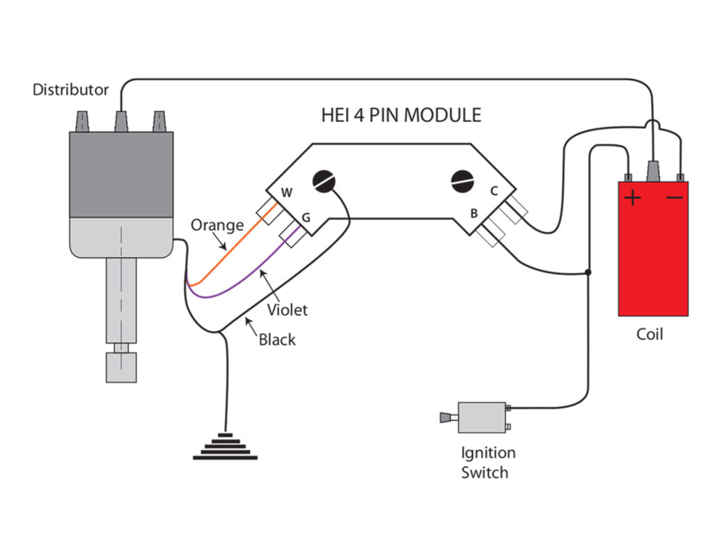
Understanding the terminology is the initial step towards finding out what kind of ignition coil you own. A simple diagram of the wiring will reveal a variety of terminals and connections, including two primary and two secondary. Each coil has an operating voltage. The first step to determine which type you have is to check the voltage at S1 or the primary terminal. You should also check S1 for resistance to determine if it’s an A or B coil.
The chassis’ negative must be connected to connect the coil’s low-tension side. This is the ground in the wiring diagram for ignition. The high-tension supply provides positive directly to spark plugs. For suppression purposes the coil’s body metal must be connected to the chassis. This is not necessary to use electricity. The diagram of the ignition wiring will also reveal the connection of the negative and positive coil’s terminals. In certain cases scanning the local auto parts store will help identify the malfunctioning ignition coils.
The black-and-white-striped wire from the harness goes to the negative terminal. The positive terminal is connected to the white wire and an trace in black. The black wire is connected to the contact breaker. You can remove the black wire from the plug housing by using a paperclip in case you are uncertain about the connection. It’s also essential to ensure that the terminals do not bend.
Accessory terminals
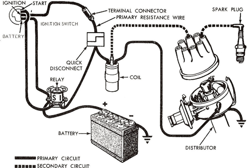
Diagrams of the ignition wiring show the wires used to power various parts of the vehicle. In general there are four distinct colored terminals for each part. The red symbol represents accessories, yellow is for the battery and green is for the starter solenoid. The “IGN” terminal can be used to turn on the car, control the wipers and other functions. The diagram shows how you can connect the ACC and ST terminals to the other components.
The battery is attached to the terminal named BAT. Without the battery the electrical system will not begin. The switch will not turn on if the battery isn’t present. You can view your wiring diagram to figure out where the batteries of your car are situated. Your car’s accessory terminals are connected to the ignition switch as well as the battery. The BAT connector is connected to your battery.
Certain ignition switches have an additional position in which users can modify their outputs and control them without the need to use the ignition. Customers sometimes want an auxiliary output that can be operated independently of the ignition. In order for the auxiliary output be used, wire the connector in the same color as that of the ignition. Then connect it with the ACC end of the switch. This is a great convenience feature, but there is one difference. Some ignition switches are configured to be in an ACC position when the vehicle has been moved into the ACC position. They’ll also be in START mode after the vehicle has been entered the IGN position.
Gallery of Ignition Points Wiring Diagram
Gallery of Ignition Points Wiring Diagram


