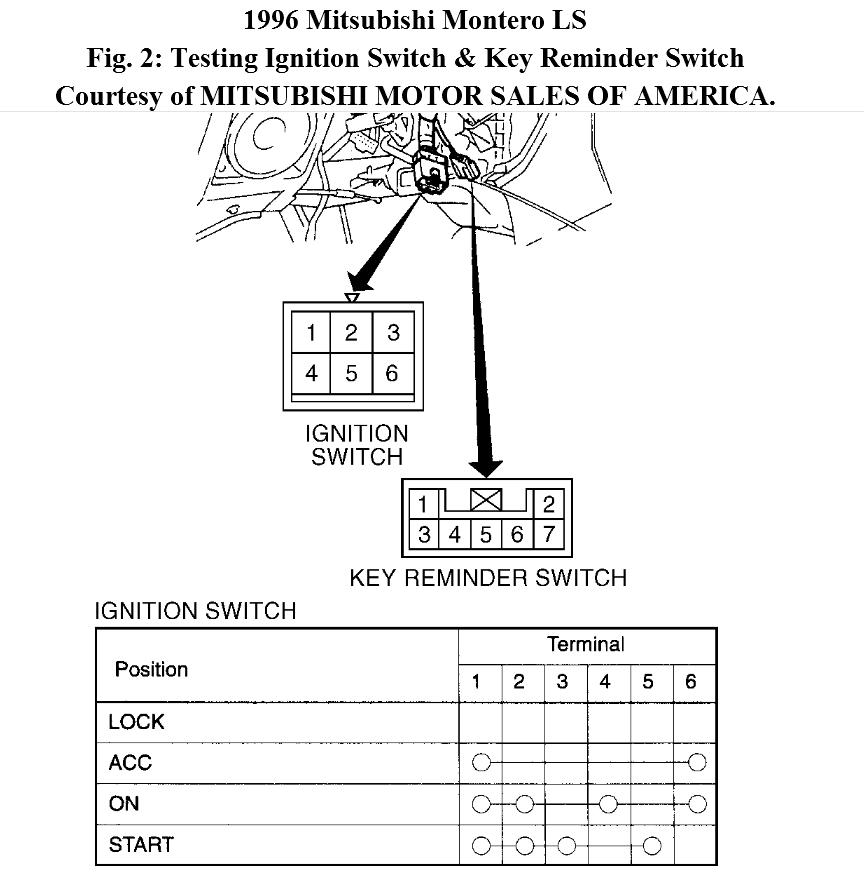
Mitsubishi Tractor Ignition Switch Wiring Diagram – The first step is to look at the different terminals on the ignition switch. These terminals serve for the Ignition button, Coil and Accessory. After we’ve identified the terminals used then we can recognize the various parts of the Mitsubishi Tractor Ignition Switch Wiring Diagram. In addition, we will discuss the functions of the Ignition switch and Coil. The next step is to focus to the accessory terminals.
The terminals are for ignition switches.
The ignition switch is comprised of three switches that supply the battery’s power to various locations. The first one is utilized to power the choke through pushing it, while the third switch is used to control the ON/OFF setting. Different manufacturers use different color-coding methods to identify different conductors. We will cover this in a different article. OMC utilizes this method. An adapter is included on the ignition switch that allows the installation of the Tachometer.
Although some ignition switch terminals do not have the original design The numbering might not be in line with the diagram. Before you plug into the ignition switch, ensure that you check the continuity. A multimeter is a great tool to test the continuity. When you’re satisfied with the integrity of the wires, then you’ll be able to connect the new connector. If your car has an installed ignition switch the wiring diagram will differ.
The first step is to understand the distinctions between the ACC and auxiliary outputs. The ACC/IGN connections function as the default connection on the ignition switch. The START/IGN terminals connect to the stereo or radio. The ignition switch turns the engine of your car ON and OFF. Older vehicles have ignition switch terminals labeled “ACC” or “ST” (for individual magnetowires).
Terminals for coil
To determine the type of ignition coil you need to know the step is to understand the terms. A simple diagram of the wiring will display a range of terminals and connections including two primary and two secondaries. Each coil has an operating voltage. The first step to determine which type you’re using is to examine the voltage at S1 or the primary terminal. To determine whether it’s an A, C, or B coil, you should also test the resistance on S1’s.
The chassis’ negative should be connected to connect to the coil’s lower-tension end. This is what’s called the ground in the wiring diagram for ignition. The high tension side supplies positive directly the spark plugs. To reduce the noise the body of the coil must be connected to the chassis. It is not necessary to electrically connect. The ignition wiring diagram will also reveal how to connect the positive and negative coil terminals. Sometimes, a malfunctioning ignition coil can be detected by a scan done in an auto parts shop.
The black-and-white-striped wire from the harness goes to the negative terminal. The white wire is black and connects to the negative terminal. The black wire connects to the contact breaker. To check the connections between the two wires use a paperclip and remove them off the housing. It’s also crucial to make sure the terminals aren’t bent.
Accessory terminals
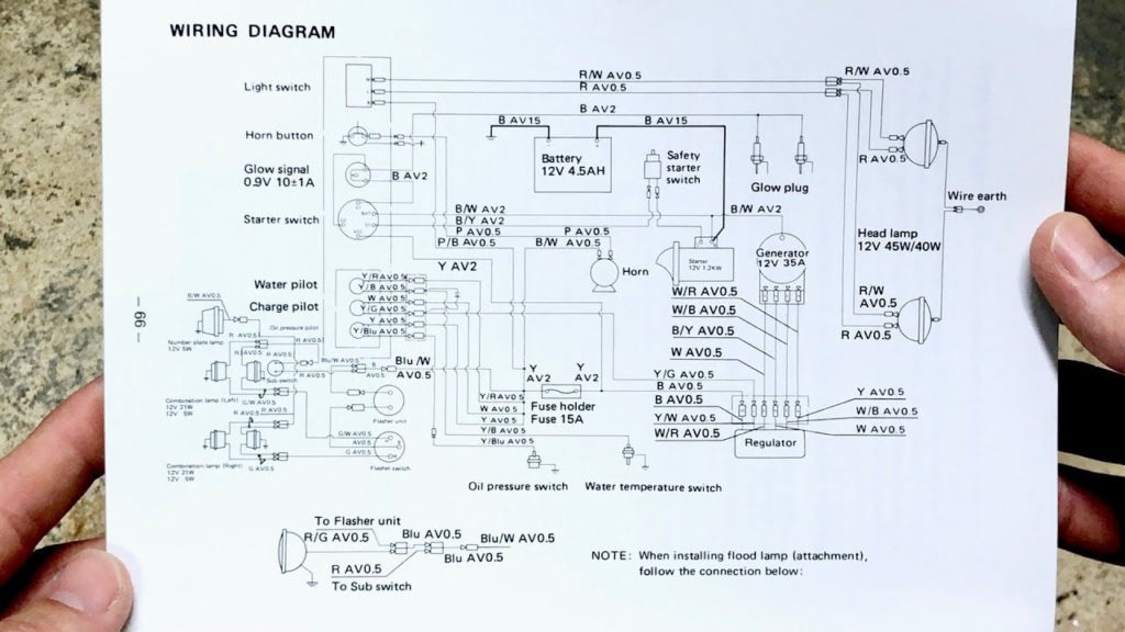
Diagrams of ignition wiring show the different wires that are utilized to power the vehicle’s various parts. Typically there are four distinct color-coded terminals for each component. Red is used to indicate accessories, yellow is the battery, and green for the starter solenoid. The “IGN” terminal can be used to start the car and operate the wipers and other operating features. The diagram demonstrates how to connect the ACC and ST terminals to the other components.
The terminal known as BAT is the place where the battery is. The electrical system will not start when the battery isn’t connected. The switch won’t turn on if the battery isn’t there. The wiring diagram will show you where to find the battery in your car. Your car’s accessory terminals connect to the ignition switch as well as the battery. The BAT terminal is connected to the battery.
Some ignition switches have an “accessory” setting that allows users to control their outputs without needing to utilize the ignition. Sometimes, a customer wants to use an auxiliary output that is separate from the ignition. The auxiliary output can be utilized by wiring the connector with the same color as your ignition and connecting it to the ACC terminal of the switch. While this is an excellent feature, there is one important difference. Most ignition switches are designed to have an ACC status when the vehicle is in either the ACC or START positions.
Gallery of Mitsubishi Tractor Ignition Switch Wiring Diagram
Gallery of Mitsubishi Tractor Ignition Switch Wiring Diagram


