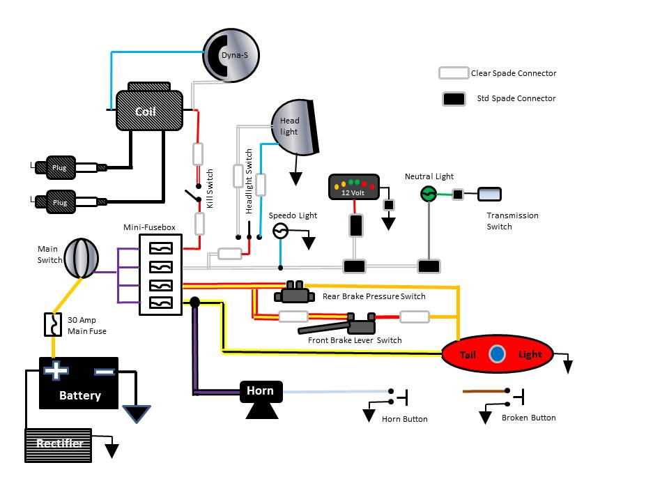
Ignition Simple Motorcycle Wiring Diagram – The first step is to take a look at the different types of terminals used on the ignition switch. They include terminals for the Ignition switch, Coil, and Accessory. After we’ve established what these kinds of terminals are We will then identify the different parts of the Ignition Simple Motorcycle Wiring Diagram. We will also cover the roles of both the Ignition Switch and Coil. We will then discuss the function of the Ignition switch as well as Coil.
Ignition switch terminals
An ignition switch has three switches. They feed the battery’s voltage to different locations. The first switch is the one that supplies power to the choke while the second toggles the on/off status of the ignition switch. Different manufacturers employ different color codes for various conductors. This is explained in a separate article. OMC uses this method. The ignition switch also includes an option to connect a timer.
Even though some ignition switch terminals don’t come in original form, the numbering may not match the diagram. To make sure that the wires are correctly plugged in to the ignition switch it is recommended to check their continuity. This can be accomplished with a multimeter that is inexpensive. After you have verified the integrity of the wires you can install the connector. If you have an ignition switch that is supplied by the manufacturer, the wiring loom is different from the one used in your vehicle.
You must first understand how the ACC outputs and the auxiliary outputs function in order to connect them. The ACC and IGN terminals are the default connections on your ignition switch, and the START and IGN terminals are the principal connections to the stereo and radio. The ignition switch switches the car’s engine on and off. The terminals for the ignition switch on older cars are labeled with the initials “ACC” as well as “ST” (for the individual magneto wires).
Terminals for coil
The language used to decide the model and type of the ignition coil is the first thing. The basic ignition wiring diagram shows a number different connections and terminals. There are two primary and secondary connections. The coils have a specific operating voltage. The first step in determining which type you’ve got is to check the voltage on S1, the main terminal. S1 must also be inspected for resistance in order to identify if it’s a Type B, B, or an A coil.
The coil’s low-tension end must be connected to the chassis positive. This is the wiring diagram you will see in the diagram of wiring. The high-tension side supplies positive directly to the spark plugs. To reduce the noise the body of the coil must be connected to chassis. But, it’s not required to connect electrically. The wiring diagram will also illustrate the connection between the positive and negative coils. In some instances, you’ll find that a malfunctioned ignition coil is identified by scans in an auto parts store.
The black-and-white-striped wire from the harness goes to the negative terminal. The other white wire has a black trace, and connects to the positive terminal. The contact breaker is attached to the black wire. If you’re not sure about the connections between the two, try using an old paper clip to take them from the plug housing. It’s also crucial to make sure the terminals don’t bend.
Accessory terminals
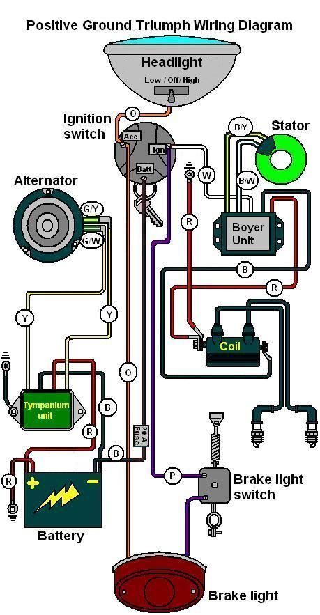
Diagrams of ignition wiring show the different wires that are utilized to power the vehicle’s various components. There are generally four colors of terminals connected to each part. The red color represents accessories, yellow for the battery and green for the starter solenoid. The “IGN” terminal allows you to start the car, manage the wipers, or any other functions. The following diagram shows how to connect both the ACC terminal as well as the ST terminals to various components.
The terminal BAT is the connection to the battery. The electrical system will not start in the event that the battery isn’t connected. The switch will not turn off if the battery isn’t there. It is possible to refer to your wiring diagram if you’re uncertain about where the car’s batteries are located. The accessory terminals on your vehicle connect to the battery as well as the ignition switch. The BAT terminal is connected to the battery.
Some ignition switches feature a separate “accessory” position, in which users can manage their outputs without the ignition. Sometimes, customers want to make use of an additional output that is independent of the ignition. In order to use the additional output, wire the connector in identical colors to the ignition, and connect it to the ACC terminal on the switch. This feature of convenience is fantastic, but there is one differentiator. Most ignition switches come with an ACC position when your car is in the ACC mode, and a START position when you are in IGN.
Gallery of Ignition Simple Motorcycle Wiring Diagram
Gallery of Ignition Simple Motorcycle Wiring Diagram


